,
DMIYI4040
and 4050
Safety and Installation Instructions
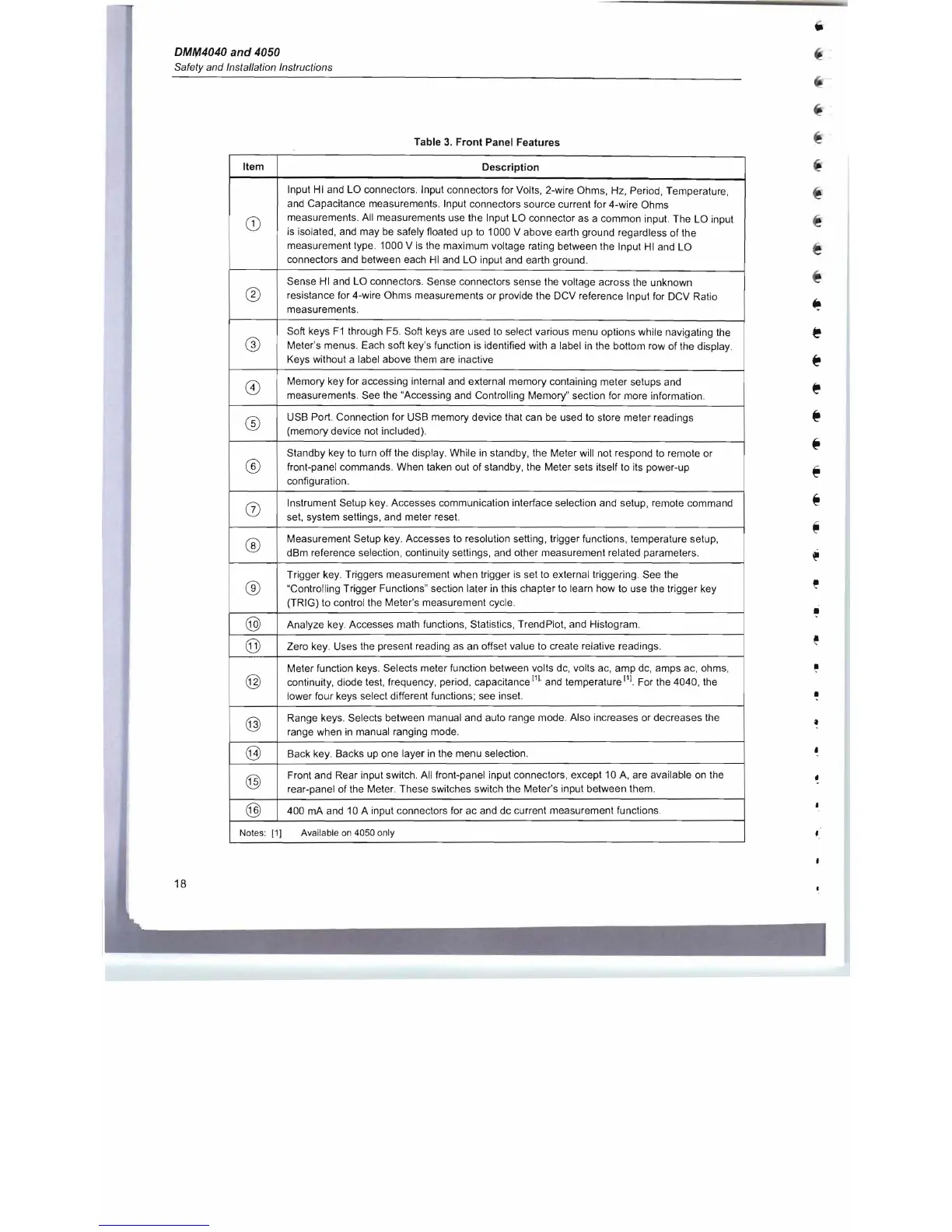
Table
3.
Front Panel Features
Item
Description
CD
Input
HI
and LO connectors. Input connectors for Volts, 2-wire Ohms, Hz, Period, Temperature ,
and
Capacitance measurements. Input connectors source current for 4-wire Ohms
measurements. All measurements use the Input LO connector as a common input. The LO input
is
isolated, and may
be
safely floated up
to
1000 V above earth ground regardless of the
measurement type . 1000 V
is
the maximum voltage rating between the Input
HI
and LO
connectors and between each
HI
and LO input and earth ground.
®
Sense
HI
and LO connectors. Sense connectors sense the voltage across
the
unknown
resistance for 4-wire Ohms measurements or provide the DCV reference Input
for
DCV Ratio
measurements.
@
Soft keys
F1
through
F5.
Soft keys are used
to
select various menu options while navigating the
Meter's menus. Each soft key's function
is
identified with a label
in
the bottom row of the display.
Keys without a label above them are inactive
8)
Memory key for accessing internal and external memory containing meter setups and
measurements. See the "Accessing and Controlling Memory" section for more information .
®
USB Port. Connection for USB memory device that can
be
used
to
store meter readings
(memory device not included).
®
Standby key
to
turn off the display. While
in
standby, the Meter will not respond
to
remote or
front-panel commands. When taken out of standby, the Meter sets itself
to
its power-up
configuration .
(])
Instrument Setup key. Accesses communication interface selection and setup, remote command
set, system settings, and meter reset.
®
Measurement Setup key. Accesses
to
resolution setting , trigger functions, temperature setup,
dBm reference selection , continuity settings, and other measurement related parameters.
®
Trigger key. Triggers measurement when trigger
is
set
to
external triggering . See the
"Controlling Trigger Functions" section later
in
this chapter to learn how
to
use the trigger key
(TRIG) to control the Meter's measurement cycle.
@
Analyze key. Accesses math functions , Statistics, TrendPlot, and Histogram.
@
Zero key. Uses the present reading
as
an
offset value
to
create relative readings.
@
Meter function keys. Selects meter function between volts dc, volts ac, amp
dc,
amps ac, ohms,
continuity, diode test, frequency, period, capacitance
[11
. and temperature
(11
For the 4040, the
lower four keys select different functions ; see inset.
@
Range keys. Selects between manual and auto range mode. Also increases or decreases the
range when
in
manual ranging mode.
@
Back key. Backs up one layer
in
the menu selection.
@
Front and Rear input switch. All front-panel input connectors , except 10
A,
are available
on
the
rear-panel of the Meter. These switches switch the Meter's input between them .
@
400
mA
and
10
A input connectors for ac and dc current measurement functions .
Notes:
[1]
Available
on
4050 only
•
,
18

 Loading...


