PS2520 Series Performance Verification
26
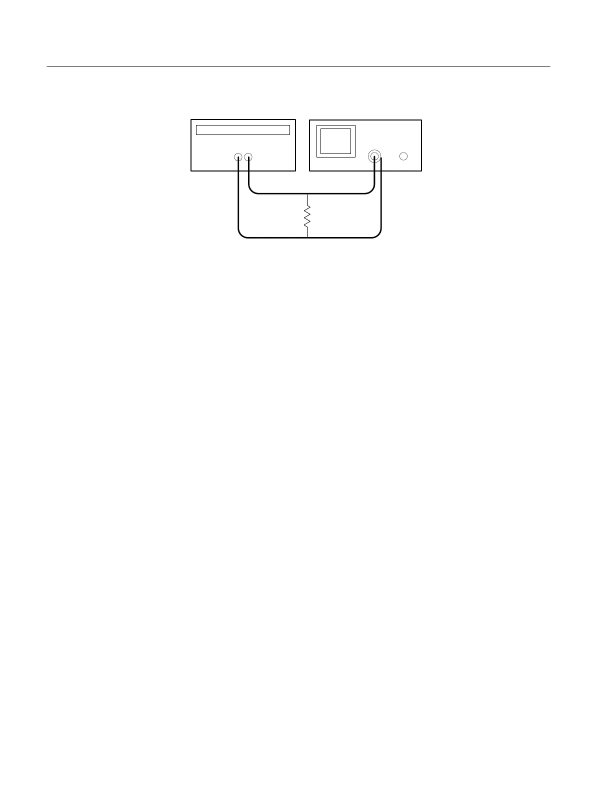
Handheld and Benchtop Instruments Basic Service
+
–
Power supply
Oscilloscope
Resistor
Figure 4: Constant Voltage Ripple and Noise Test Setup
3. Set up the oscilloscope to measure 100 mV
p-p
(AC coupled
).
4. Set up the power supply as follows:
VOLTS SET 36 V
CURRENT SET 1.55 A
OVP SET 38.5 V
5. Press OUTPUT ON/OFF. Verify that the “C.V.” indicator lights up on the
display.
6. Using a 0.1 mF ceramic capacitor to decouple the test points, adjust the
oscilloscope and verify that the noise is ≤30 mV
p-p
.
7. Set the oscilloscope to LINE trigger source. Adjust the output of the Variac
from 108 to 132 VAC (120V range) or 198 to 242 VAC (220V range). Verify
that the ripple changes ≤3 mV
p-p
over the adjustment range.
8. Press OUTPUT ON/OFF. Verify that the “OUT” indicator turns off.
9. Press SHIFT
→ OUT 2; verify that the “2” indicator lights up on the display.
10. Ensure that the power supply output is disabled. Remove the leads from the
front panel OUTPUT 1 terminals and connect them to the front panel
OUTPUT 2 terminals. Maintain the equipment configuration and polarities
shown in Figure 4.
11. Repeat steps 4 through 8 above.
Outputs 3. Use the following steps to check the OUTPUT 3 accuracy.
1. Press SHIFT
→ OUT 3; verify that the “3” indicator lights up on the display.
 Loading...


