PS2520 Series Performance Verification
Handheld and Benchtop Instruments Basic Service
27
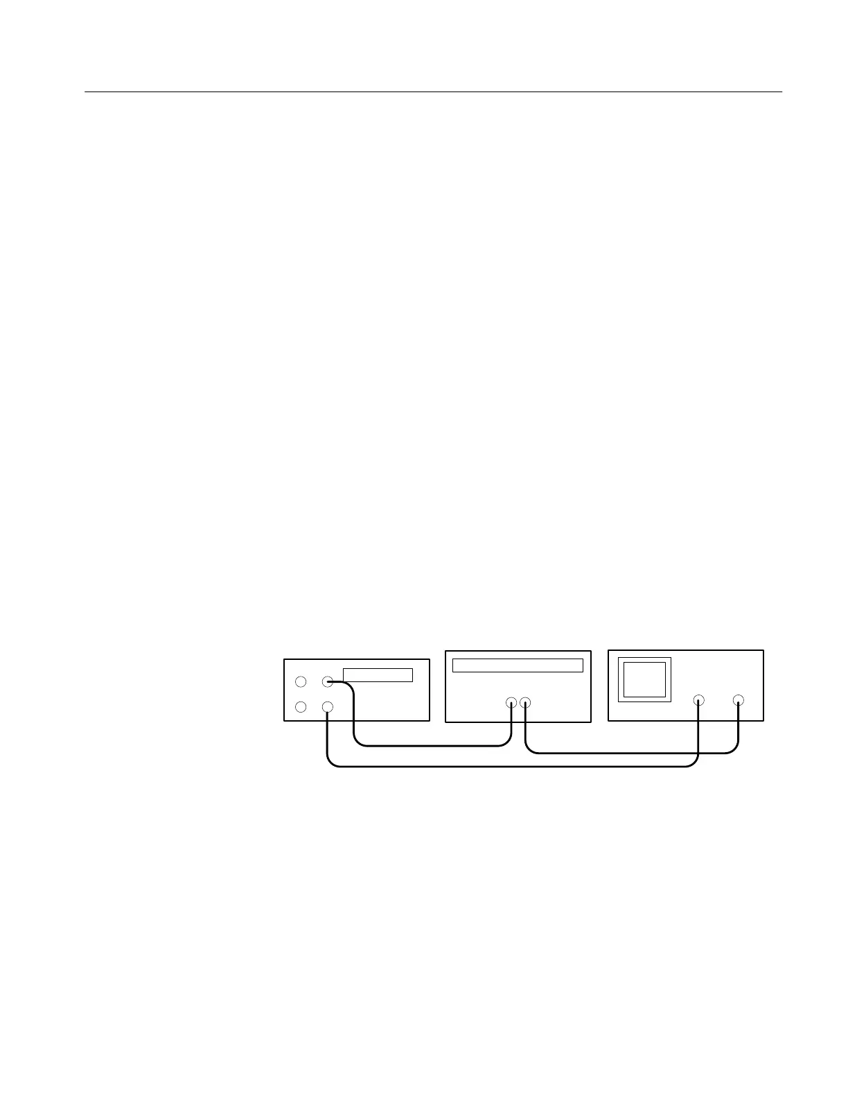
2. Ensure that the power supply output is disabled. Connect the oscilloscope
and 2.2 W 50 W resistor to the front panel OUTPUT 3 terminals. See Figure
4 for details.
3. Set up the power supply as follows:
VOLTS SET 6 V
CURRENT SET 3.1 A
OVP SET 7 V
4. Repeat steps 5 through 8 of the Outputs 1 and 2 procedure above.
5. Remove the Variac from the test setup and repower the instrument. Allow 20
minutes for the power supply to warm-up and stabilize before the next check.
Complete the following procedures to verify constant current load and overcur-
rent protection accuracy.
Outputs 1 and 2. Use the following steps to check the OUTPUT 1 and
OUTPUT 2 accuracy.
1. Press SHIFT
→ OUT 1; verify that the “1” indicator lights up on the display.
2. Ensure that the power supply output is disabled. Connect the DMM and
electronic load to the front panel OUTPUT 1 terminals. See Figure 5 for
details.
Electronic load
Power supply
+
–
–
+
Digital multimeter
+–
10 A
COM
Figure 5: Constant Current Load Test Setup
3. Set the DMM to measure 2 amperes DC.
4. Set up the power supply as follows:
VOLTS SET 36 V
CURRENT SET 1.5 A
OVP SET 38.5 V
Constant Current Load
and Overcurrent
Protection Accuracy
 Loading...


