PS2520 Series Performance Verification
28
Handheld and Benchtop Instruments Basic Service
5. Press OUTPUT ON/OFF. Verify that the “OUT” indicator lights up on the
display.
6. Enable the electronic load. Adjust the load until the “C.C.” indicator lights
up on the power supply display.
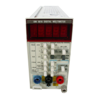
7. Record the DMM current reading (I1).
8. Press OUTPUT ON/OFF. Verify that the “OUT” indicator turns off.
9. Ensure that the power supply output is disabled. Remove the wire connect-
ing the power supply OUTPUT (+) terminal to the electronic load (+)
terminal.
10. Move the electronic load (–) connection, to the power supply OUTPUT (+)
terminal.
11. Press OUTPUT ON/OFF. Verify that the “OUT” indicator lights up on the
display.
12. Record the DMM current reading again (I2).
13. Verify that the difference between (I1) and (I2) is ≤0.003 A.
14. Press OUTPUT ON/OFF. Verify that the “OUT” indicator turns off.
15. Press OCP ON/OFF. Verify that the “OCP” indicator lights up on the
display.
16. Press OUTPUT ON/OFF. Verify that the “OUT” indicator lights up on the
display.
17. Verify that the power supply readouts display the error message “Err - 012”.
18. Press OUTPUT ON/OFF. Verify that the “OUT” indicator turns off.
19. Press OCP ON/OFF to return the power supply to normal operation. Verify
that the “OCP” indicator turns off.
20. Press SHIFT
→ OUT 2; verify that the “2” indicator lights up on the display.
21. Ensure that the power supply output is disabled. Connect the DMM and
electronic load to the front panel OUTPUT 2 terminals. Maintain the
equipment configuration and polarities shown in Figure 5.
22. Repeat steps 4 through 18 above.

 Loading...


