PS2520 Series Performance Verification
30
Handheld and Benchtop Instruments Basic Service
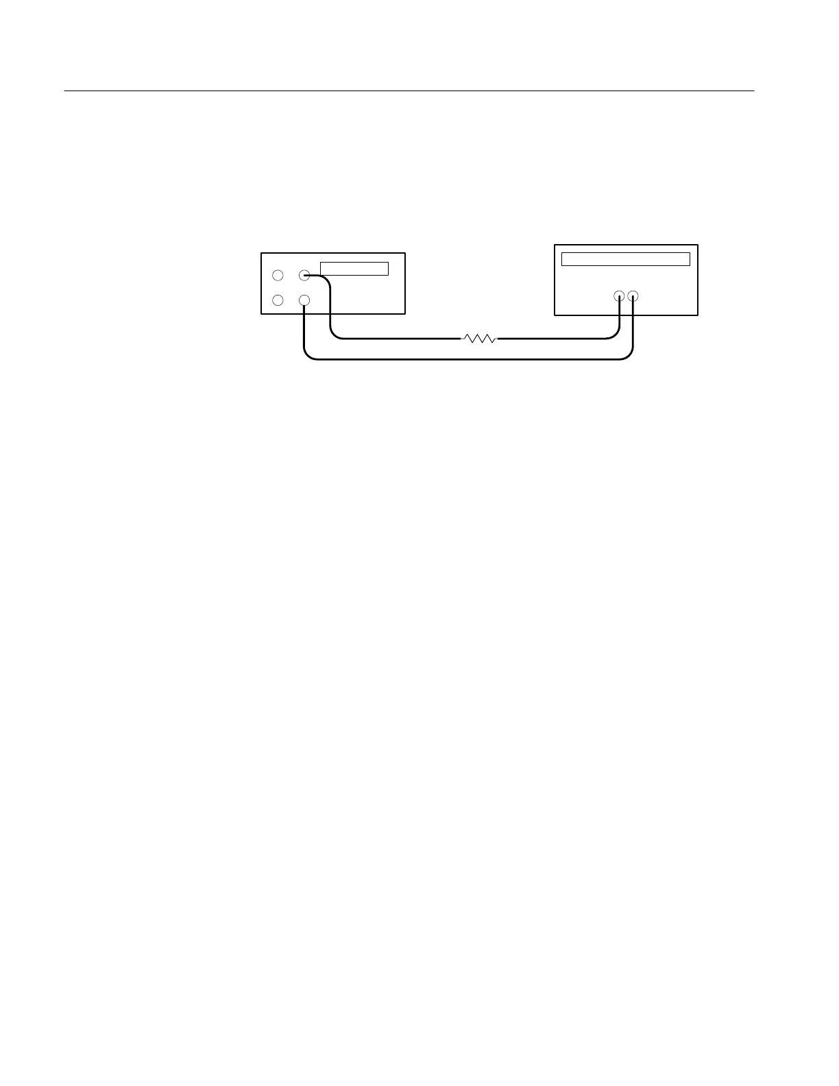
2. Ensure that the power supply output is disabled. Connect the DMM and
27 W 100 W resistor to the front panel OUTPUT 1 terminals. See Figure 6
for details.
Power supply
+
–
–
+
Digital multimeter
10 A
COM
Resistor
Figure 6: Constant Current Source Test Setup
3. Set the DMM to measure 2 amperes DC.
4. Press SHIFT
→ OUT 1; verify that the “1” indicator lights up on the display.
5. Set up the power supply as follows:
VOLTS SET 36 V
CURRENT SET 1.5 A
OVP SET 38.5 V
6. Press OUTPUT ON/OFF. Verify that the “OUT” indicator lights up on the
display.
7. Adjust the output of the Variac from 108 to 132 VAC (120V range) or 198 to
242 VAC (220V range). Verify that the DMM current variation is ≤0.003 A
over the adjustment range.
8. Press OUTPUT ON/OFF. Verify that the “OUT” indicator turns off.
9. Press (SHIFT) OUT 2; verify that the “2” indicator lights up on the display.
10. Ensure that the power supply output is disabled. Remove the leads from the
front panel OUTPUT 1 terminals and connect them to the front panel
OUTPUT 2 terminals. Maintain the equipment configuration and polarities
shown in Figure 6.
11. Repeat steps 5 to 8 above.
Parallel Operation. Use the following steps to check the parallel mode output
accuracy.
1. Press SHIFT
→ OUT 2; verify that the “2” indicator lights up on the display.
 Loading...


