THM420 Adjustment Procedures
16
Handheld and Benchtop Instruments Basic Service
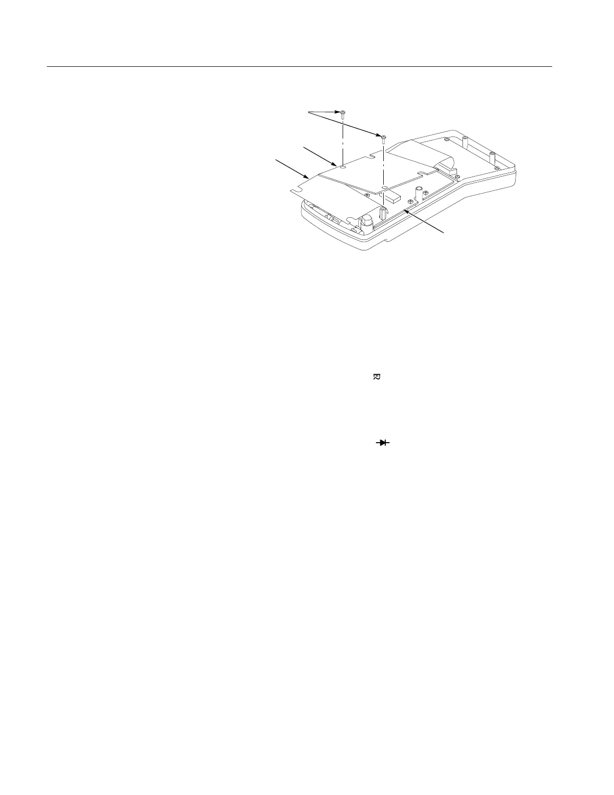
Lift and position circuit board
Fold back shield
Mounting screws
Main circuit board
Figure 3: Exposing the Main Circuit Board
Adjustment Procedure
To return your instrument to factory calibration, perform the following
procedure.
1. Turn the THM420 rotary switch to V
.
2. Press the METER/SCOPE button to select SCOPE mode.
3. Set the AC/DC button to DC.
4. Connect the COM input to the V W Hz
input with a shorting strap.
5. Set the vertical offset (POS) to 0 mV.
6. Set the vertical SCALE to 200 V.
7. Adjust R80 to align the trace to the display center line. See Figure 4 for the
adjustment location.
8. Set the vertical scale to 20 mV.
9. Adjust R84 to align the trace to the display center.
10. If necessary, repeat steps 5 through 9 above to achieve a fine adjustment.
 Loading...


