PS2520 Series Performance Verification
Handheld and Benchtop Instruments Basic Service
49
+
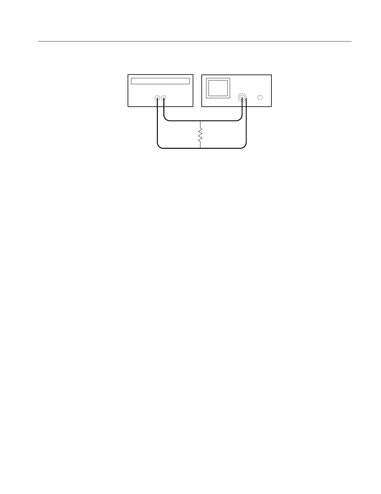
–
Power supply
Oscilloscope
Resistor
Figure 9: Constant Voltage Ripple and Noise Test Setup
3. Set up the oscilloscope to measure 100 mV
p-p
(AC coupled).
4. Set up the power supply as follows:
VOLTS SET 36 V
CURRENT SET 2.55 A
OVP SET 38 V
5. Press OUTPUT ON/OFF. Verify that the “C.V.” indicator lights up on the
display.
6. Using a 0.1 mF ceramic capacitor to decouple the test points, adjust the
oscilloscope and verify that the noise is ≤30 mV
p-p
.
7. Set up the oscilloscope to LINE trigger source. Adjust the output of the
Variac from 108 to 132 VAC (120 V range) or 198 to 242 VAC (220 V
range). Verify that the ripple changes ≤3 mV
p-p
over the adjustment range.
8. Press OUTPUT ON/OFF. Verify that the “OUT” indicator turns off.
9. Press SHIFT
→ OUT 2; verify that the “2” indicator lights up on the display.
10. Ensure that the power supply output is disabled. Remove the leads from the
front panel OUTPUT 1 terminals and connect them to the front panel
OUTPUT 2 terminals. Maintain the equipment configuration and polarities
shown in Figure 4.
11. Repeat steps 4 through 8 above.
Outputs 3. Use the following steps to check the OUTPUT 3 accuracy.
1. Press SHIFT
→ OUT 3; verify that the “3” indicator lights up on the display.
 Loading...


