PS2520 Series Performance Verification
Handheld and Benchtop Instruments Basic Service
53
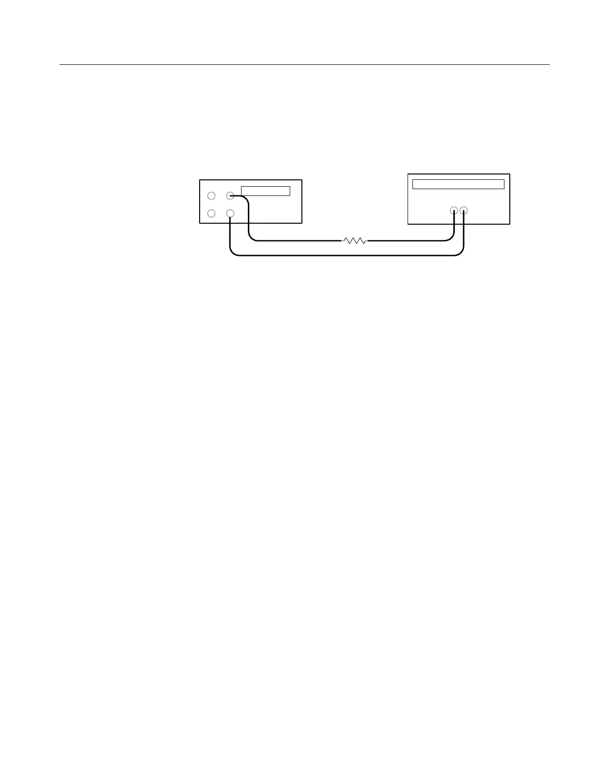
2. Ensure that the power supply output is disabled. Connect the DMM and
27 W 75 W resistor to the front panel OUTPUT 1 terminals. See Figure 6 for
details.
Power supply
+
–
–
+
Digital multimeter
10 A
COM
Resistor
Figure 11: Constant Current Source Test Setup
3. Set the DMM to measure 5 amperes DC.
4. Press SHIFT
→ OUT 1; verify that the “1” indicator lights up on the display.
5. Set up the power supply as follows:
VOLTS SET 20 V
CURRENT SET 2.5 A
OVP SET 22 V
6. Press OUTPUT ON/OFF. Verify that the “OUT” indicator lights up on the
display.
7. Adjust the output of the Variac from 108 to 132 VAC (120 V range) or 198
to 242 VAC (220 V range). Verify that the DMM current variation is
≤0.003 A over the adjustment range.
8. Press OUTPUT ON/OFF. Verify that the “OUT” indicator turns off.
9. Press SHIFT
→ OUT 2; verify that the “2” indicator lights up on the display.
10. Ensure that the power supply output is disabled. Remove the leads from the
front panel OUTPUT 1 terminals and connect them to the front panel
OUTPUT 2 terminals. Maintain the equipment configuration and polarities
shown in Figure 6.
11. Repeat steps 5 to 8 above.
Parallel Operation. Use the following steps to check the parallel mode output
accuracy.
1. Press SHIFT
→ OUT 2; verify that the “2” indicator lights up on the display.
 Loading...


