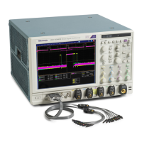
Do you have a question about the Tektronix DPO7054C and is the answer not in the manual?
Provides essential safety precautions for product operation and to prevent injury or damage.
Details precautions related to fire and personal injury, including power cord usage and grounding.
Outlines safety procedures specifically for qualified personnel performing service on the product.
Lists EMC standards and directives the instrument complies with for electromagnetic compatibility.
Details safety standards, certifications, and listings for national and international safety compliance.
Provides information about the product's environmental impact and end-of-life handling.
Specifies the environmental and operational conditions required for the instrument.
Details measures to prevent Electrostatic Discharge (ESD) damage to the instrument's input.
Outlines the power supply requirements and power consumption for the instrument.
Provides instructions on how to disconnect or remove the power source from the instrument.
Details the procedure for restoring the instrument's operating system from its hard disk.
Provides instructions for installing or replacing the hard drive in specific instrument models.
Outlines the procedure to run internal diagnostics and verify the instrument's functionality.
Details the procedure for signal path compensation to ensure measurement accuracy.
Guides users on connecting probes and selecting input channels for analog signal acquisition.
Directs users to online help for procedures on compensating passive probes and deskewing channels.
Explains the FastAcq mode for capturing transient events and phenomena at high speed.
Details how to use DSP enhanced bandwidth for more accurate measurements and extended bandwidth.
Guides users on connecting logic probes and setting up digital channels for signal acquisition.
Details how to set digital channel thresholds, size, position, and labels.
Explains how to set up serial and parallel buses for data analysis.
Provides instructions for setting up serial bus parameters and selecting bus types.
Details how to set up parallel bus parameters and select channels as sources.
Describes the iCapture function for viewing analog characteristics of digital signals.
Explains fundamental concepts of trigger events, modes, and holdoff for accurate triggering.
Details how to select and configure various trigger types available on the instrument.
Lists and describes different trigger types and their corresponding trigger conditions.
Guides users on using A and B triggers for capturing complex signal sequences.
Explains B-Event Scan for creating overlapped eye diagrams synchronized with A trigger events.
Guides users on setting up triggers for parallel bus analysis using digital channels.
Details how to set up triggers for serial bus analysis, covering various protocols.
Explains how to create trigger conditions directly on the display screen using visual areas.
Details how to use Wave Inspector controls for efficient management of long record length waveforms.
Details how to use the Serial Error Detector for analyzing serial data and detecting errors.
Explains how to compare signals to predefined masks for pass/fail testing.
Guides users on comparing active signals to template waveforms for pass/fail testing.
Provides a procedure for capturing intermittent anomalies using FastAcq mode and trigger settings.
Explains how to set up triggers for various bus types, including serial and parallel protocols.
Explains how to use the iView capability to correlate analog and digital data from oscilloscopes and logic analyzers.
Outlines crucial safety precautions for using the probe and its accessories to prevent hazards.
| Bandwidth | 500 MHz |
|---|---|
| Channels | 4 |
| Sample Rate | 5 GS/s |
| Vertical Resolution | 8 bits |
| Input Coupling | AC, DC, GND |
| Record Length | 25 M points |
| Input Impedance | 1 MΩ ±1% |
| Display | 12.1 in. |
| Trigger Modes | Edge, Pulse Width |
| Operating Temperature | 0 °C to 40 °C |
| Maximum Input Voltage | 300 V RMS (1 MΩ), 5 V RMS (50 Ω) |


