Getting Acquainted with the Oscilloscope
the expected nu
merical measurement if a vertical clipping condition exists.
Part of the waveform is above or below the display. To obtain a proper
numerical measurement, turn the vertical scale and position knobs to make all
of the w aveform appear in the display.
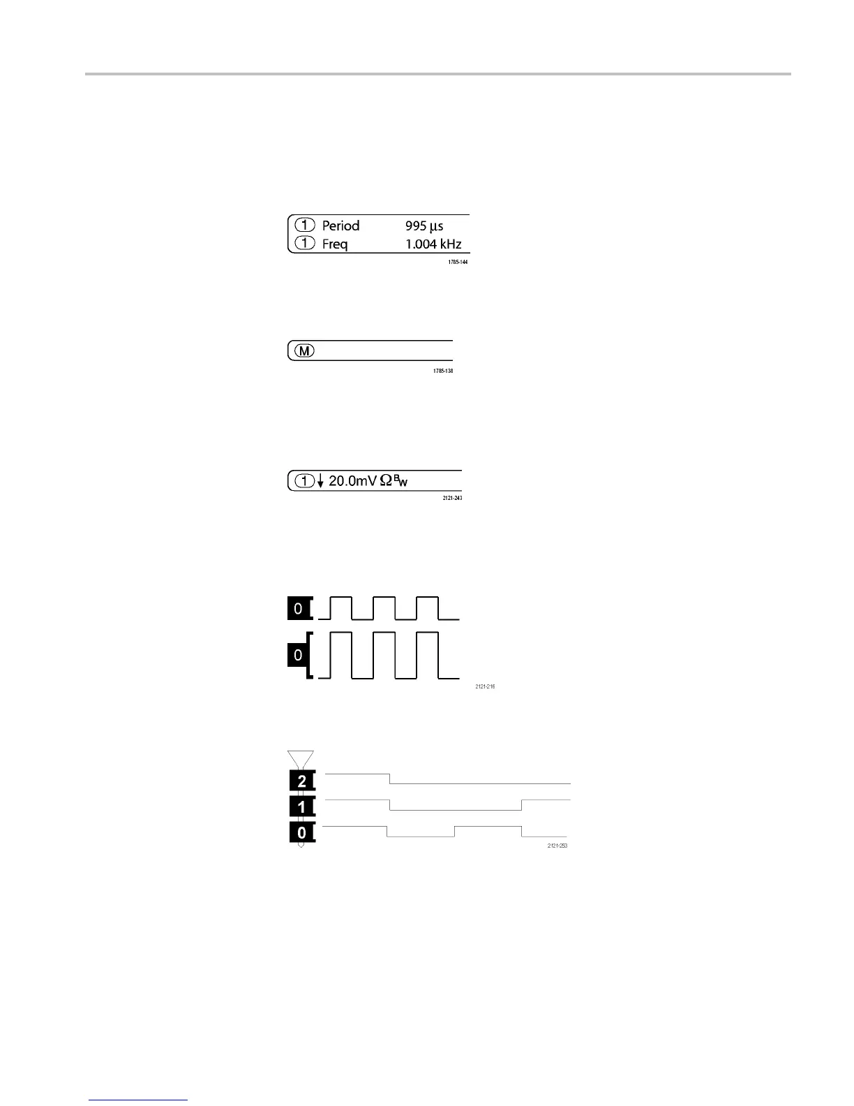
14. The auxiliary waveform readouts show the vertical and horizontal scale
factors of the math and refe rence waveforms.
15. The channel readout shows the channel scale factor (per division), coupling,
invert, and bandwidth status. Adjust with the Vertical Scale knob and in the
channel 1, 2, 3,or4 menus.
16. For digital channels, the baseline indicators point to the high and low levels.
The indicator colors follow the color code used on resistors. The D0 indicator
is black, the D1 indicator is brown, the D2 indicator is red, and s o on.
17. The group icon indicates when digital channels are grouped.
18. The bus display shows decoded packet level information for serial buses or
for parallel buses. The bus indicator shows the bus number and bus type.
19. For analog channels, the waveform baseline indicator shows the zero-volt
level of a waveform, assuming you have not used any offset. The icon colors
correspond to the waveform colors.
MDO3000 Installation and Safety Instructions 41
 Loading...


