• If the Probe Compensation Status field displays Pass, the probe is compensated and ready for use.
•
If the Probe Compensation Status field displays Default, the attached probe has not been compensated and needs to have this probe
compensation procedure run.
• If the Probe Compensation Status field displays Fail, the attached probe has failed the probe compensation procedure. Reconnect the
probe and run probe compensation again.
• If there is no probe compensation status field shown in the panel, the oscilloscope cannot store compensation values for that probe.
See the oscilloscope Help for how to manually compensate passive probes not supported by the probe compensation function.
• Each compensation generates values for a specific probe and channel combination. If you want to use the probe on another channel
and desire to compensate the new probe-channel pair, you must run a new set of compensation steps.
• Each channel can store compensation values for 10 individual probes. If you try to compensate an 11th probe on a channel, the
oscilloscope will delete the values for the least recently used probe and add the values for the new probe.
Use this procedure to compensate a TPP0250, TPP0500B, TPP1000, or other supported TPP-family probe that shows a Default status
when connected to the oscilloscope.
Note: A Default Setup does not delete probe compensation values. A factory calibration deletes all stored probe compensation
values.
Before you begin
The oscilloscope must be powered on for at least 20 minutes before compensating a probe.
Procedure
1. Connect a supported probe to an input channel.
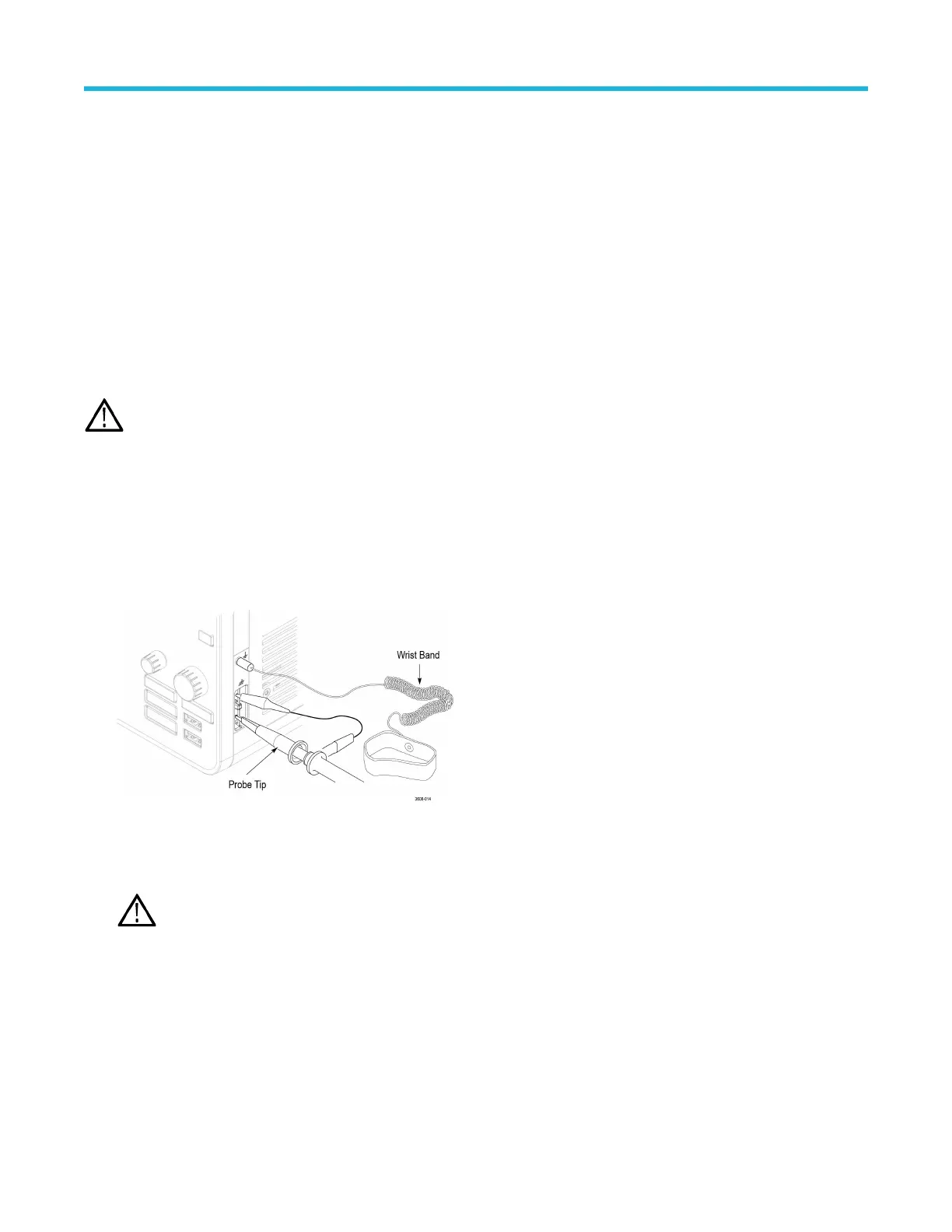
2. Connect the probe tip and ground lead of the probe to the PROBE COMP terminals on the lower right of the oscilloscope (see
following image).
Figure 2: Probe Comp connections.
Connect the probe tip to the 1 kHz source and the ground clip to the ground. For best results, remove any probe tip accessories and
hold the probe tip directly onto the 1 kHz connector
.
Note: Connect only one probe at a time to the PROBE COMP terminals.
3. Turn off all channels.
4. Turn on the channel to which the probe is connected.
5. Push the front-panel Autoset button. The screen displays a square wave.
6. Double-tap the badge of the channel that you want to compensate.
7. Tap the Probe Setup panel.
If the Probe Compensation Status says Pass, the probe is already compensated for this channel. You can move the probe to another
channel and start again from step 1 or connect a different probe to this channel and start from step 1.
If the Probe Compensation Status says Default, continue with this procedure.
Configure the instrument
3 Series Mixed Domain Oscilloscope MDO32 and MDO34 Quick Start Manual 35