EasyManuals Logo
Home>Tektronix>Test Equipment>MSO2000 series

Tektronix MSO2000 series Instruction Manual

Tektronix MSO2000 series
132 pages
To Next Page IconTo Next Page
To Previous Page IconTo Previous Page
Page #121 background imageLoading...
Page #121 background image
Locating Signals
The SPI bus signals are set as follows:
SCLK is the rising edge latch
SS is active low
MOSI is active high
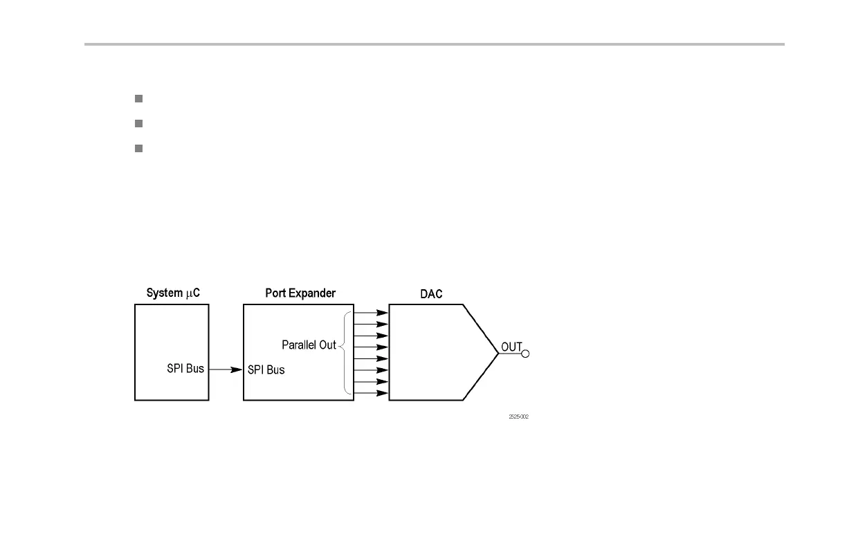
This is the beginning of the mixed signal chain. See the descriptions of these signals: DAC Input, Parallel, and DAC Output.
Packets occur approximately every 5 ms. The SPI packet contents are transferred to the Parallel DAC Input bus at the end of the
packet. The Parallel DAC Input bus then changes the voltage output of the DAC.
TheresultingDACoutputisasinewavewithanamplitudeof0to3volts,andaperiodof310ms.
The clock rate is a 100 kHz, 0 to 5 volt signal.
Figure 2: Mixed sign al chain block diagram
Demo 2 Board Instruction Manua l 115

Table of Contents

Other manuals for Tektronix MSO2000 series

Questions and Answers:

Question and Answer IconNeed help?

Do you have a question about the Tektronix MSO2000 series and is the answer not in the manual?

Tektronix MSO2000 series Specifications

General IconGeneral
BrandTektronix
ModelMSO2000 series
CategoryTest Equipment
LanguageEnglish

Related product manuals