Acquire the Signal
Physical Layer Bus Activity
Oscilloscope wave form traces fro m analog channels 1 to 4, digital channels D15 to D0, and the traces you see when you choose to
display a bus always show the physical layer bus activity. In the physical layer display, bits that were transmitted earlier are to
the left, and bits that were transmitted later are to the right.
I2C, and CAN b uses transmit the MSB (most significant bit) first
SPI buses do not specify a bit order
RS-232 and LIN buses transmit the LSB (least significant bit) first
NOTE. The o scilloscope displays the decode traces and event tables for all buses with the MSB on the left and LSB on the right.
For example, an RS-232 sign al (after the start bit) might be high, high, high, low, high, low, low, and high. Since the RS-232 protocol
uses high for zero and low for one, this value would be 0001 0110.
Since the decode displays the MSB first, the oscilloscope reverses the order of the bits an d displays 0110 1 000. If the bus display is
set to hex, the value displays as 68. If the bus display is set to ASCII, the value displays as h.
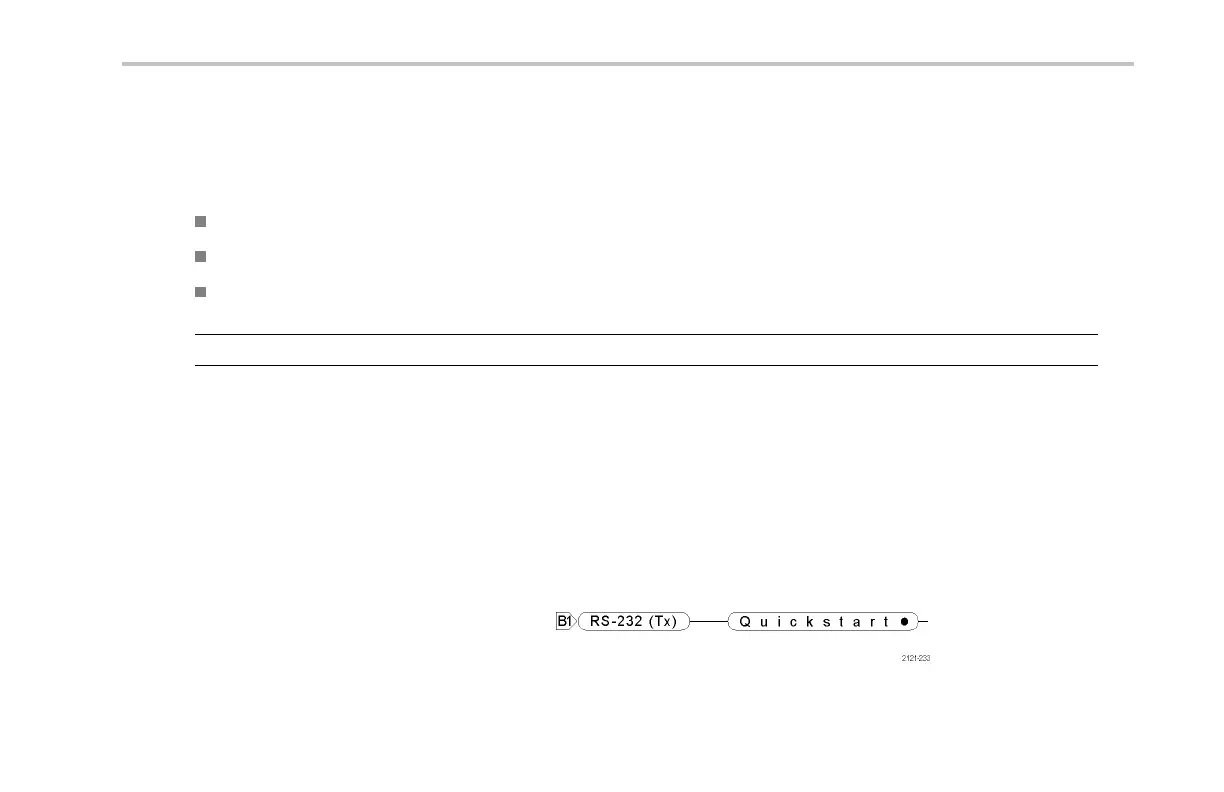
RS-232
If you defined an end-of-packet character to
use for RS-232 decoding, the stream of bytes
will be displayed as packets.
DPO2000 and MSO2000 Series Oscilloscopes User Man ual 111