Home
Tektronix
Test Equipment
MSO4000B Series
Tektronix MSO4000B Series Service Manual
4
of 1
of 1 rating
53 pages
Give review
Manual
Specs
To Next Page
To Next Page
To Previous Page
To Previous Page
Loading...
Maintenance
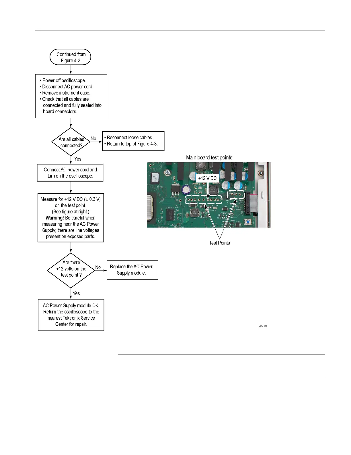
Figure
6:
AC
power
supply
troubleshooting
procedure
NOTE.
The
test
point
voltages
are
printed
on
the
Main
boar
d.
From
left
to
right
in
the
illustration,
they
are:
+1.225
V
,
-1.2
V
,
-2.5
V
,
+1.5
V
,
-5
V
,
+12
V
,
+1.8
V
,
+5
V
A,
+5
VSB,
and
+2.5
V
,
+3
.3
V
,
+5
V
.
MSO4000B
and
DPO4000B
Series
Digital
Phos
phor
Oscilloscopes
Service
Manual
27
38
40
Table of Contents
Table of Contents
5
General Safety Summary
8
Preface
11
Manual Conventions
11
Where to Find Operating Information
13
Theory of Operation
15
Power Supply
15
I/O Board
15
Main Board and Analog Board
15
Front-Panel Board
16
Figure 1: Four-Channel Model MSO4000B and DPO4000B Series Block Diagram
17
Figure 2: Two-Channel Model MSO4000B and DPO4000B Series Block Diagram
18
Adjustment Procedure
19
Required Equipment
19
Before Adjustments
20
Navigating During Adjustments
20
Connecting the Equipment
21
Factory Adjustment Procedure
22
Setting the Calibrator Output Signal
25
Maintenance
31
Preventing ESD
31
Inspection and Cleaning
31
Table 1: External Inspection Checklist
33
Table 2: Internal Inspection Checklist
33
Module Removal
35
Figure 3: Removing Tabs from the Front Protective Cover
35
Figure 4: Module Locator
36
Troubleshooting
37
Troubleshooting Procedure
37
Figure 5: Primary Troubleshooting Procedure
38
Figure 6: AC Power Supply Troubleshooting Procedure
39
Figure 7: Module Isolation Troubleshooting Procedure
40
Unpacking and Repacking Instructions
41
Replaceable Parts List
43
Parts Ordering Information
43
Using the Replaceable Parts List
44
Table 3: Parts List Column Descriptions
44
Table 4: Replaceable Parts - Front Panel Assembly
45
Figure 8: Exploded View, Front Panel Assembly
46
Table 5: Replaceable Parts - Display, Analog Board, and Main Board
47
Figure 9: Display, Analog Board, and Main Board Assembly
48
Table 6: Replaceable Parts - Rear Chassis and Connecting Modules
49
Figure 10: Rear Chassis and Connecting Modules
50
Figure 11: External Parts
51
Table 7: Replaceable Parts - External Parts
51
Figure 12: Rear Chassis, Showing Cables and Connectors
52
Table 8: Replaceable Parts - Cable and Connectors, Rear Chassis
52
Figure 13: Main Board, Showing Cable and Connectors
53
Table 9: Replaceable Parts - Cable and Connectors, Main Board
53
Other manuals for Tektronix MSO4000B Series
User Manual
229 pages
Technical Reference
87 pages
4
Based on 1 rating
Ask a question
Give review
Questions and Answers:
Need help?
Do you have a question about the Tektronix MSO4000B Series and is the answer not in the manual?
Ask a question
Tektronix MSO4000B Series Specifications
General
Brand
Tektronix
Model
MSO4000B Series
Category
Test Equipment
Language
English
Related product manuals
Tektronix MSO4000 Series
359 pages
Tektronix MSO4054
359 pages
Tektronix MSO4034
359 pages
Tektronix MSO4032
359 pages
Tektronix MSO46
43 pages
Tektronix MSO44
43 pages
Tektronix MSO46B
43 pages
Tektronix MSO4104
359 pages
Tektronix MSO4104B
53 pages
Tektronix MSO56B
143 pages
Tektronix MSO2024B
152 pages
Tektronix MSO5034B
222 pages