Performance Verification
9. Adjust the Vert
ical POSITION knob to center the time mark signal on the
screen.
10. Adjust the Trigger LEVEL knob as necessar y for a triggered display.
11. Adjust the Horizontal POSITION knob to move the trigger location to the
center of the screen (50%).
12. Turn the Horizontal POSITION knob counterclockwise to set the delay to
exactly 80 ms.
13. Set the Horizontal Scale to 400 ns/div.
14. Compare the rising edge of the marker with the center horizontal graticule
line. The rising edge should be within ±1 divisions of center graticule. Enter
the deviation in the test record.
NOTE. One division of displacement from graticule center c orresponds to a
5 ppm time base error.
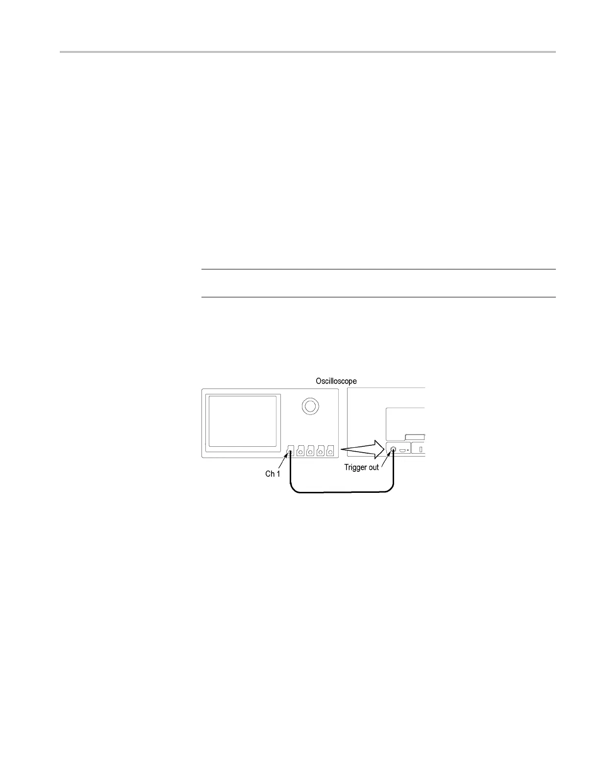
Check Trigger Out
This test chec ks the Trigger Output.
1. Connect the Trigger Out signal from the rear of the instrument to the channel
1 input using a 50 Ω cable.
2. Push the front-panel Default Setup button to set the instrument to the factory
default settings.
3. Push the channel 1 button.
4. Set the oscilloscope impedance to 1 MΩ. The default Impedance setting
is 1MΩ.
5. Set the horizontal to 4 μS/div and the vertical to 1 V/div.
6. Push the front-panel Wave Inspector Measure button.
7. Push the Add Measurement lower-bezel button.
8. Use the Multipurpose a knob to select the Low measurement.
9. Push the OK Add Measurement side bezel button.
MSO4000 and DPO4000 Series Specifications and Performance Verification 45
 Loading...


