Procedure:
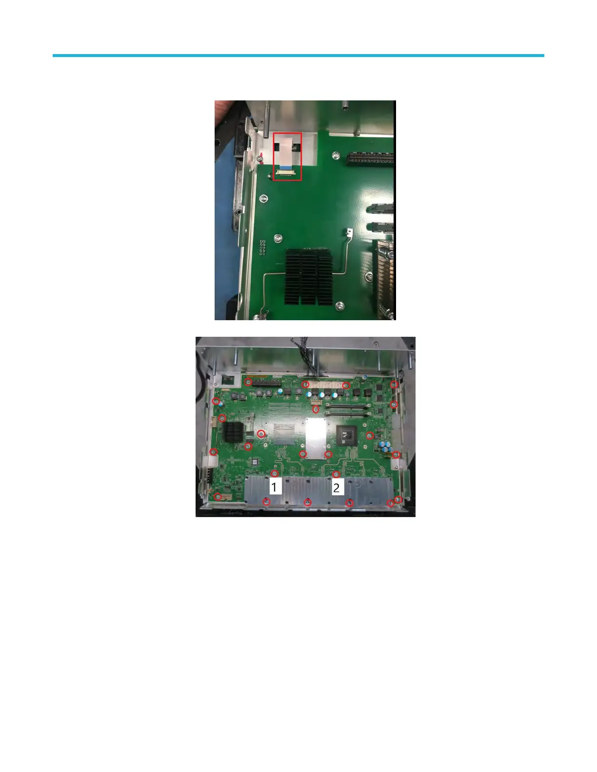
1. Disconnect the front panel cable from the main board as shown below
.
2. Use a T-10 Torx screwdriver to remove the 23 screws that have attached the main board to the front chassis assembly .
3. T
o reinstall, reverse the above steps. Tighten the T-10 Torx screws to 0.65 N·m when reinstalling.
Remove the processor board
The following procedure describes the removal and replacement of the processor board.
Prerequisite:
• To prevent electrostatic damage to components whenever you work on the instrument, wear properly-grounded electrostatic prevention
wrist and foot straps, and work in a tested antistatic environment on an antistatic mat.
• Remove the front chassis assembly.
Procedure:
1. Use a T-10 Torx screwdriver to remove the seven screws that have attached the processor board to the front chassis assembly.
Maintenance
4 Series MSO (MSO44, MSO46) Service 28