Verify the time base.
Equipment required Prerequisites
<4 GHz models: One precision 50 Ω coaxial
cable (Item 4)
<4 GHz models: One BNC to Minigrabber
adapter (item 18)
≥4 GHz models: One SMA cable (item 21)
≥4 GHz models: One adapter (item 19)
None
1. Initialize the instrument: Push the front-panel Default Setup button.
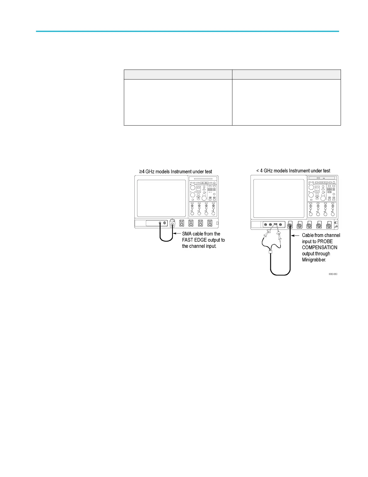
2. Hook up the signal source: Connect the probe compensation or fast edge
output to the Ch 1 input as shown in the following figure.
Figure 4: Setup for time base test
3. Set up the instrument: Push the front panel Autoset button.
4. Set the Vertical Scale to 200 mV /div (≤20 GHz models) or 120 mV/div
(>20 GHz models).
5. Set the time base: Set the horizontal Scale to 200 μs/div. The time-base
readout is displayed at the bottom of the graticule.
6. Verify that the time base operates: Confirm the following statements.
■
One period of the square-wave signal is about five horizontal divisions
on-screen for the 200 μs/div horizontal scale setting.
■
Rotating the horizontal Scale knob clockwise expands the waveform on-
screen (more horizontal divisions per waveform period),
counterclockwise rotation contracts it, and returning the horizontal scale
to 200 μs/div returns the period to about five divisions.
■
The horizontal Position knob positions the signal left and right on-screen
when rotated.
Performance verification (MSO/DPO70000C, MSO/DPO70000DX, and DPO7000C series)
MSO70000C/DX, DPO70000C/DX, DPO7000C, MSO5000/B, DPO5000/B Series 107
 Loading...