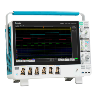
Do you have a question about the Tektronix MSO64B and is the answer not in the manual?
Summary of general safety precautions for safe operation and to prevent damage.
Outlines specific precautions to prevent fire hazards and personal injury during use.
Guidelines for safe handling and connection of probes and test leads to prevent shock.
Additional safety information specifically for performing service procedures on the product.
Explains terms and symbols used in the manual and on the product for hazard identification.
Lists the specific instrument models covered by this service manual.
Defines what constitutes a replaceable part and how they are referenced.
Directs users to other resources for installation, operation, and networking details.
Describes the electrical operation and module interconnections via block diagram.
Details the power supply board's role in converting AC line voltage to internal power.
Outlines the various functions integrated within the carrier interface assembly.
Explains the processor system's control functions, storage, and I/O interfaces.
Lists and describes the connectivity ports located on the instrument's rear panel.
Describes the acquisition system, front-end processing, and power conversion roles.
Details the front panel controls, display interface, and probe compensation signal generation.
States that adjustment and calibration must be performed by a Tektronix Service Center.
Provides recommendations for periodic performance verification and adjustment frequency.
Outlines the mandatory performance verification after module replacement.
Details crucial precautions to prevent damage from ESD during servicing.
Describes methods for inspecting for damage and cleaning the instrument.
Instructions for cleaning the external surfaces of the instrument safely.
Specific instructions for safely cleaning the instrument's display screen.
Guidance on cleaning internal components, focusing on the rear chassis assembly.
Notes that no periodic lubrication is required for this instrument.
Instructions for proper packaging and shipping of the instrument for repair.
Lists the necessary equipment and antistatic work environment setup.
Steps for safely removing and reinstalling the front panel knob assemblies.
Procedure to remove the external hard drive SATA riser board assembly.
Instructions for removing the instrument's bottom foot assemblies.
Steps for removing and replacing the instrument's handle assemblies.
Procedure to remove the rear grill and rear case from the instrument.
Steps to detach and remove the rear chassis assembly.
Procedure to remove the baffle bracket for access to other components.
Detailed steps for the safe removal of the power supply unit.
Procedure for removing the carrier interface assembly.
Steps to remove the AFG riser assembly from the carrier interface.
Procedure to remove the handle hubs from the rear chassis.
Steps to remove the main fan assembly from the rear chassis.
Details required skills and support contacts for troubleshooting.
A table listing frequent issues and their potential root causes.
Lists the essential tools needed for effective fault diagnosis.
A visual guide to systematically diagnose and resolve instrument faults.
Explains the meaning and behavior of the instrument's status LEDs.
Step-by-step guide to diagnose potential power supply failures.
Instructions for running and interpreting built-in diagnostic tests for hardware and software.
Procedure to download diagnostic log files for further analysis by support.
Guidance on downloading and installing the latest instrument firmware.
Specific steps for updating firmware using a USB drive.
Steps to perform after replacing the power supply module, including verification.
Instructions and necessary details for ordering replacement components.
Describes choices for module exchange, repair, or purchasing new modules.
A list of abbreviations conforming to ANSI standards used in the manual.
Explains how to interpret the components listed in the replaceable parts sections.
Lists and illustrates replaceable components for the instrument's enclosures.
Details replaceable parts for the carrier interface and rear chassis assemblies.
Lists and illustrates replaceable parts for the baffle and power supply modules.
Lists and illustrates replaceable components for the mid-plane chassis assembly.
Details replaceable parts associated with the front panel and display assembly.
| Brand | Tektronix |
|---|---|
| Model | MSO64B |
| Category | Test Equipment |
| Language | English |


