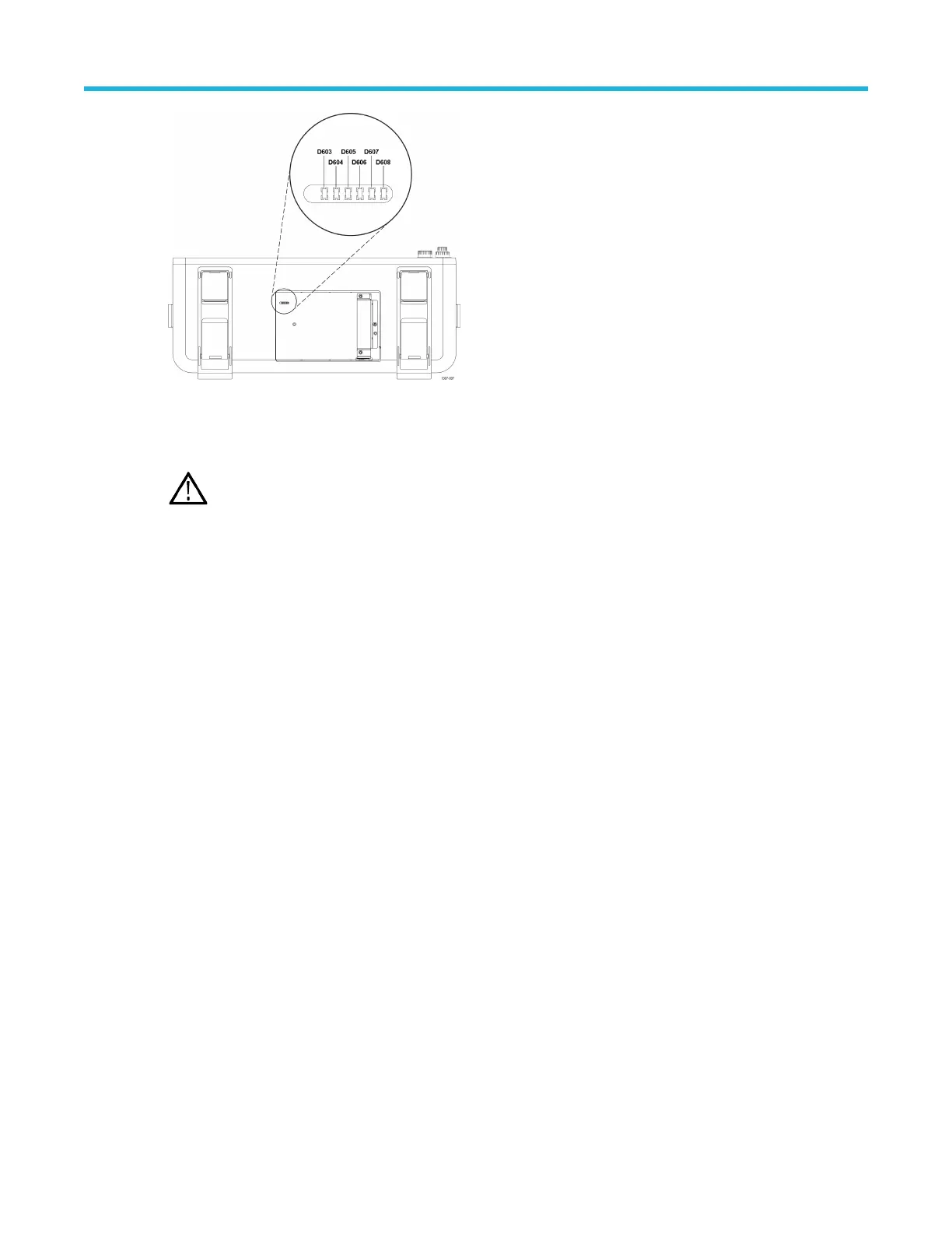
Figure 3: Power status LEDs
All of these LEDs should be green a few moments after powering on the instrument. If any of these LEDs are red, or are not
lit, return the instrument to a T
ektronix Service Center for repair.
Note: Before you send the instrument to T
ektronix for repair, make sure that each LED status is recorded and
attached the recordsheet with the instrument.
Troubleshoot the power supply
Use this procedure to determine if the power supply is defective and needs replaced.
Before you begin
Prerequisites:
•
To prevent electrostatic damage to components whenever you work on the instrument, wear properly-grounded
electrostatic prevention wrist and foot straps, and work in a tested antistatic environment on an antistatic mat.
• Remove rear chassis assembly on page 11
• Remove the baffle bracket on page 12
Procedure
1. Connect the power cord to the AC connector on the back of the rear chassis.
2. Measure for +12 V
DC
between chassis and pin 10 of J3203 (large connector). If there is +12 V
DC
at pin 10, go to step 3
on page 23. If you do not measure +12 V
DC
at Pin 10 of J3203 connected to the circuit board:
Maintenance
6 Series B MSO MSO64B, MSO66B, MSO68B Service 22