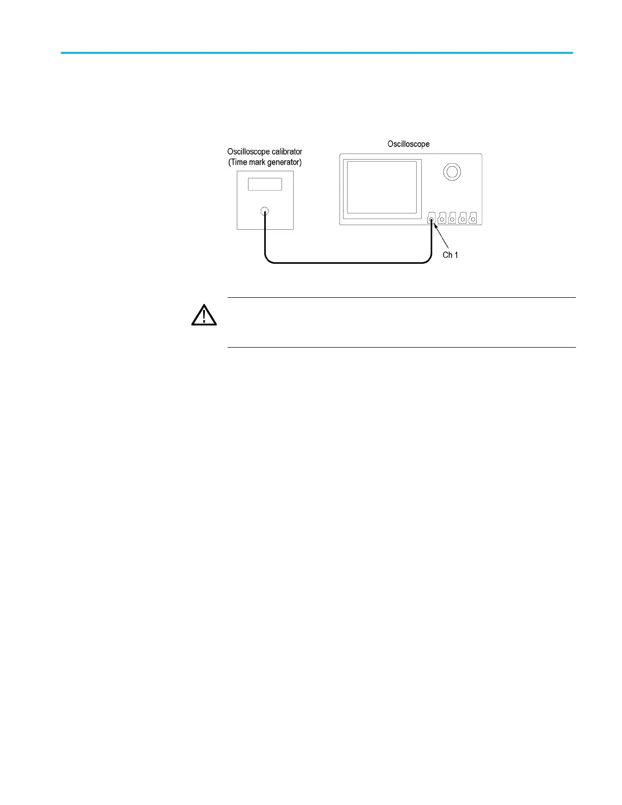
1. Connect the output of a time mark generator to the oscilloscope
channel 1 input using a 50 Ω cable, as shown in the following illustration.
WARNING. The generator is capable of providing dangerous voltages. Be
sure to set the generator to off or 0 volts before connecting, disconnecting,
and/or moving the test hookup during the performance of this procedure.
2. Set the time mark generator period to 80 ms. Use a time mark waveform with
a fast rising edge.
3. Push the front-panel Default Setup button.
4. Set the impedance to 50 Ω as follows:
a. Push the front-panel oscilloscope Vertical V menu button.
b. Set the Termination to 50 Ω.
5. If it is adjustable, set the time mark amplitude to approximately 1 Vp-p.
6. Set the Vertical Scale to 500 mV.
7. Set the Horizontal Scale to 20 ms/div.
8. Set the Vertical Position to center the time mark signal on the screen.
9. Set the Trigger Level as necessary for a triggered display.
10. Adjust the Horizontal Position to move the trigger location to the center of
the screen (50%).
11. Set the delay to 80 ms as follows:
a. Push the front-panel Acquire button. Ensure that the Horizontal tab on
the left side of the screen is selected.
b. Turn Delay on.
c. Turn the Horizontal Position knob clockwise (or click the Delay box and
use the keypad) to set the delay to exactly 80 ms.
12. Set the horizontal scale to 500 ns/div using the Horizontal Scale knob or by
clicking in the Scale box and using the up/down arrows.
Performance verification (MSO/DPO5000/B series)
MSO70000C/DX, DPO70000C/DX, DPO7000C, MSO5000/B, DPO5000/B Series 331
 Loading...