TM 11-6625-2980-14
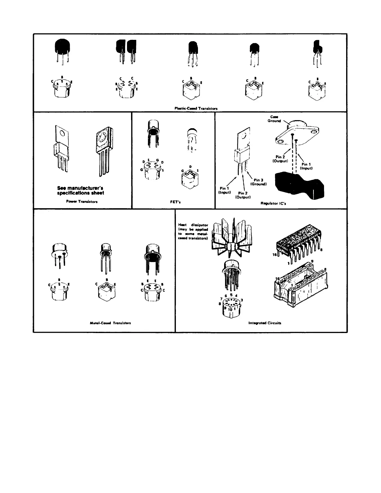
Replacement semiconductors should be of the
original type or a direct replacement. The above figure
shows the lead configuration of the semiconductors
used in this instrument system. When removing
soldered-in transistors, use a suction-type de-soldering
tool to remove the solder from the holes in the circuit
board.
An extracting tool should be used to remove the 14-
and 16-pin integrated circuits to prevent damage to the
pins. If an extracting tool is not available, use care to
avoid damaging the pins. Pull slowly and evenly on both
ends of the IC. Try to avoid having one end of the IC
disengage from the socket before the other end.
To replace one of the power transistors mounted on
the Power Module chassis adjacent to the interface
circuit board, first unsolder the leads. Then, loosen the
nuts which clamp the transistor to the chassis. Remove
the defective transistor. When replacing the transistor,
use a mica washer on the metal tab to increase heat
transfer from the transistor to the chassis.
A-11