TM 11-6625-2980-14
Interconnecting Pins. To replace a pin which is
mounted on a circuit board, first disconnect any pin
connectors. Then, unsolder the damaged pin and pull it
out of the board with a pair of pliers. Be careful not to
damage the wiring on the board with too much heat.
Ream out the hole in the circuit board with a 0.031-inch
drill. Remove the ferrule from the new interconnecting
pin and press the new pin into the hole in the circuit
board. Position the pin in the same manner as the old
pin. If the old pin was bent at an angle to mate with a
connector, bend the new pin to match the associated
pins.
Cam Switches. Repair of cam type switches should
be undertaken only by experienced maintenance
personnel. Switch alignment and spring tension of the
contacts must be carefully maintained for proper
operation of the switch.
The cam-type switches consist of rotating cam
drums which are turned by front-panel knobs, and sets
of spring-leaf contacts mounted on adjacent circuit
boards. The contacts are actuated by lobes on the
cams. These switches can be disassembled for
inspection, cleaning, repair, or replacement as follows:
1. Remove the screws which hold the metal cover
on the switch, and lift the cover off the switch. The
switch is now open for inspection or cleaning.
2. To completely remove a switch from the circuit
board, first remove any knobs or shaft extensions.
Loosen the coupling at the potentiometer at the rear of
the switch, and pull the long shaft out of the switch
assembly.
3. Remove the screws (from the opposite side of
the circuit board) which hold the cam drum to the board.
4. To remove the cam drum from the front support
block, remove the retaining ring from the shaft on the
front of the switch and slide the cam drum out of the
support block. Be careful not to lose the small detent
roller.
5. To replace defective switch contacts, follow the
instructions given in the switch repair kit.
6. To re-install the switch assembly, reverse the
above procedure.
Pushbutton Switches. The pushbutton switches
are not repairable and should be replaced as a unit if
defective. Use a suction-type de-soldering tool to
remove solder from the circuit board when removing
these switches.
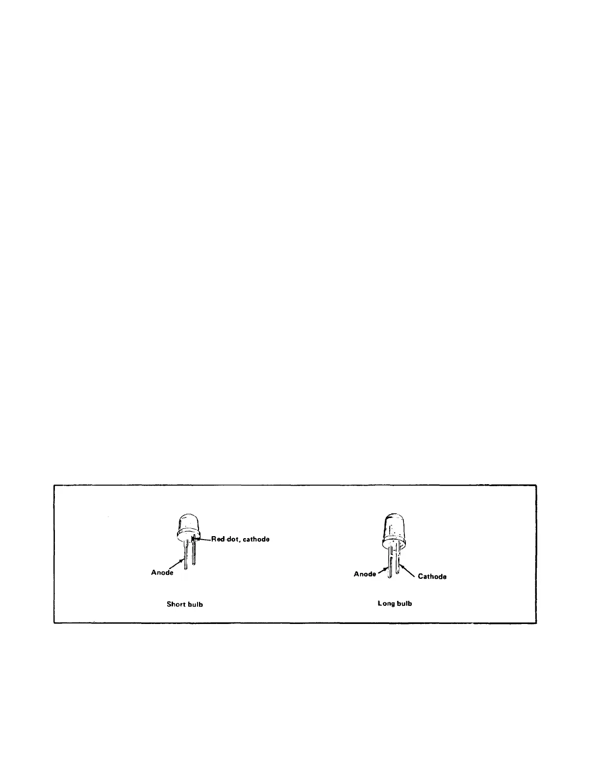
Light-Emitting Diodes. LED's used as indicators
are mounted on the sub-panels with plastic sleeve
sockets similar to the incandescent bulb mountings or
they are soldered directly to a sub-assembly and so
mounted that they protrude through holes in the panel.
In these cases, the sub-assembly must be exposed and
the anode and cathode lead orientations carefully noted
before unsoldering the defective LED. See figure below
for LED lead identifying information.
A-12