Getting Started
The current pro
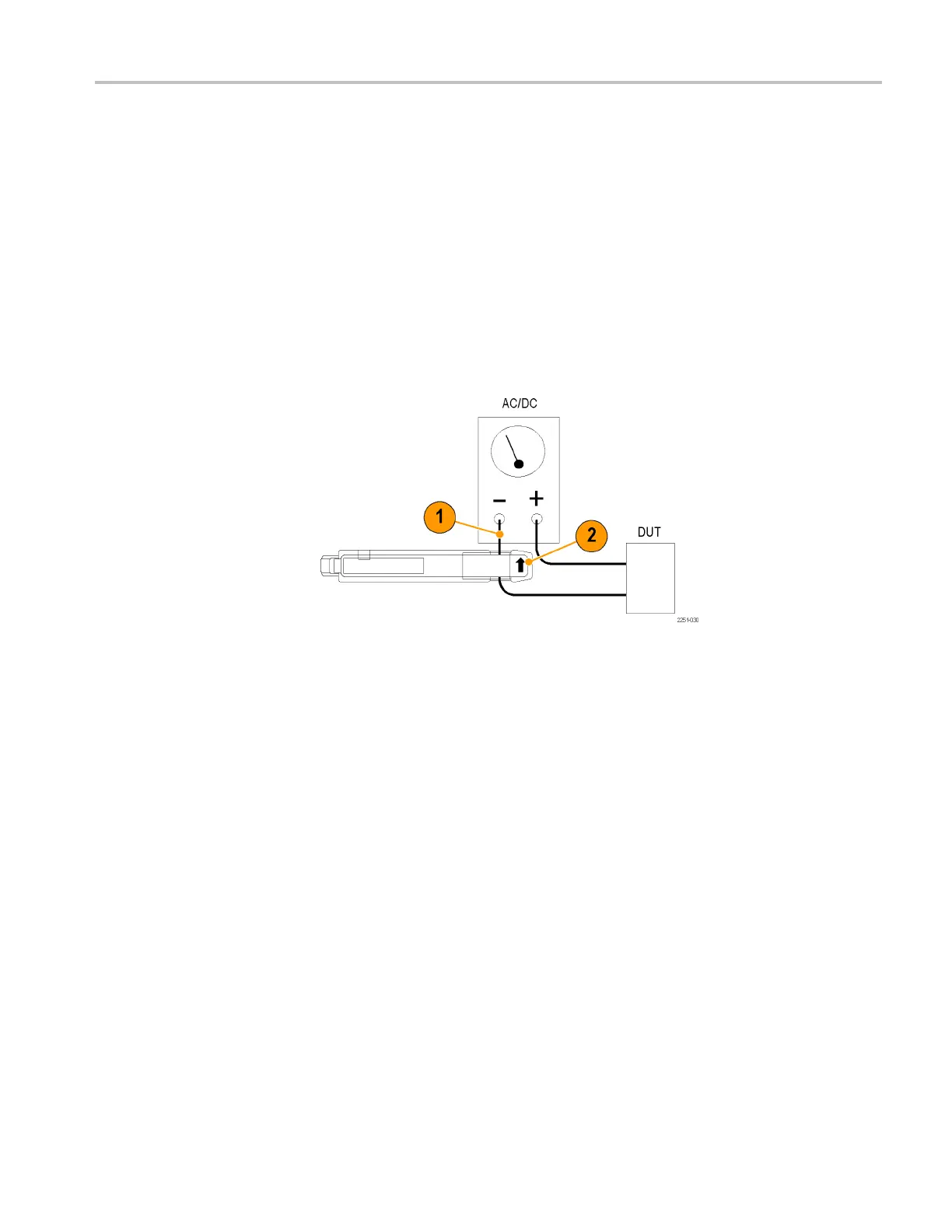
be is shown connected to a power supply line. (See Figure 8.)
Notice that the probe arrow points toward the negative terminal of the power
supplytoconf
orm to the conventional current flow of positive (+) to negative (-).
To measure DC current, perform these steps:
1. Open the pro
be slide, place the probe around the conductor under test, and
then lock the slide.
2. For correct
measurement polarity, make sure the probe arrow is pointing in
the d irection of conventional (positive to negative) current flow. Reversing
the flow will display the current waveform upside-down on the oscilloscope.
3. Adjust the oscilloscope time b ase, trigger, and gain as needed.
Figure 8: Current probe polarity
TCPA300/400 Amplifiers and TCP300/400 Series Current Probes User Manual 13
 Loading...


