Maintenance
TDS 200 Series Digital Oscilloscope Service Manual
6–45
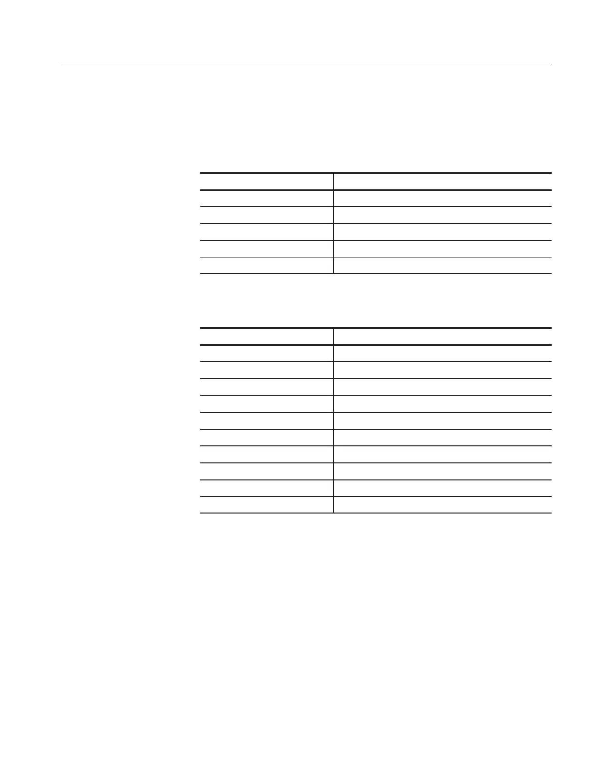
9. Use the test oscilloscope and set the Attenuation switch to 10X on the P2100
probe to probe the front panel module cable connector at J603 (two channel
oscilloscopes) or J103 (four channel oscilloscopes) on the main board. The
table below describes the signals you should expect to see.
Signal J603 Description
1 FDCLR
Positive Pulses, 100 ns wide (typical), 280 ms period
2 +5 V +5 V
3 FPCLR
Negative clock pulses, 100 ns wide (typical), 4.5 ms period
4 GND 0 V (ground)
5 FPDATA
Negative pulse burst, 300 ms period (typical)
Signal J103 Description
1 GND (0 V)
2
Negative clk pulse, 80 ns wide, 4.5 ms period (typical)
3
Positive pulse, 100 ns wide (typical), 280 ms period
4
Positive pulse, 100 ns wide, 280 ms period (typical)
5
Negative pulse, 80 ms wide, 4.5 ms period (typical)
6 GND (0 V)
7
Negative pulse burst, 300 ms (typical)
8 +5 V
9
Negative pulse burst, 300 ms (typical)
10 —14 V (typical)
10. If all of the signals are present, the front panel board is probably defective.
Replace it.
11. If some or all of the signals are missing, continue with step 12.
12. Turn the instrument off and disconnect the front panel module cable from the
main board at connector J603 or J103.
13. Turn on the instrument and check connector J603 or J103 for the same
signals as in step 9.
14. If some or all of the signals are missing, the main board is probably
defective. Replace it.

 Loading...


