Specifications
1–2
TDS 200 Series Digital Oscilloscope Service Manual
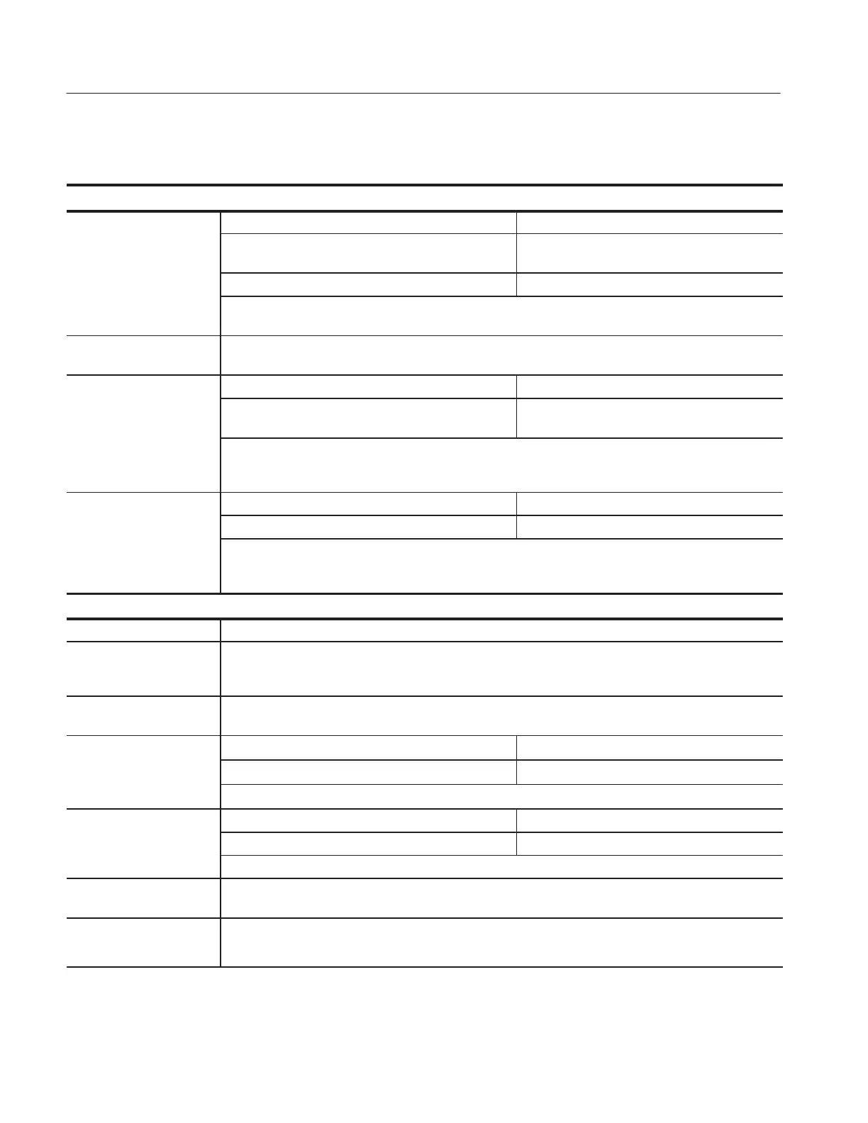
Table 1–1: Specifications (cont.)
Inputs
Maximum Voltage Between Overvoltage Category Maximum Voltage
Probe Tip and ground
using P2100 connected to
CAT I and CAT II
300 V
RMS
(500 V peak, duty factor < 35%, pulse
width < 100 msec.)
input BNC
CAT III
100 V
RMS
Derate at 20 dB/decade above 900 kHz to 13 V
RMS
at 27 MHz* and above. Also, refer to Overvoltage
Category description on page 1–7.
Time delay between
channels, typical
150 ps
Channel-to-Channel TDS 210 TDS 220 and TDS 224
Common Mode Rejection,
typical
100:1 at 60 Hz
20:1 at 30 MHz*
100:1 at 60 Hz
20:1 at 50 MHz*
Measured on MATH Ch1 – Ch2 waveform, with test signal applied between signal and common of both
channels, and with the same VOLTS/DIV and coupling settings on each channel. Also measured on MATH
Ch3 – Ch4 waveform for the TDS 224.
Channel-to-Channel Cross- TDS 210 TDS 220 and TDS 224
talk
w100:1 at 30 MHz*
w100:1 at 50 MHz*
Measured on one channel, with 8 division test signal applied between signal and common of the other
channel, the same VOLTS/DIV and coupling settings on each channel, and 50 W terminators on each
channel.
Vertical
Digitizers 8 bit resolution (except when set to 2 mV/div), each channel sampled simultaneously
VOLTS/DIV Range 2 mV/div to 5 V/div at input BNC
(Full bandwidth at u5 mV/div to 5 V/div, 20 MHz at 2 mV/dif to 5 mV/div, except in Peak Detect mode full
bandwidth at u10 mV/div to 5 V/div [20 MHz at 2 mV/div to 10 mV/div])
Position Range 2 mV/div to 200 mV/div, ±2 V
> 200 mV/div to 5 V/div, ±50 V
n Analog Bandwidth in
TDS 210 TDS 220 and TDS 224
Sample and Average modes
60 MHz* (when vertical scale set to > 5 mV/div) 100 MHz* (when vertical scale set to > 5 mV/div)
at BNC or with P2100 probe,
DC Coupled
20 MHz
* (when vertical scale set to ≤ 5 mV/div)
Analog Bandwidth in Peak TDS 210 TDS 220 and TDS 224
Detect mode (5 s/div to
50 MHz* (when vertical scale set to > 10 mV/div) 75 MHz* (when vertical scale set to > 10 mV/div)
5
s/div), typical
20 MHz
* (when vertical scale set to ≤ 10 mV/div)
Selectable Analog Band-
width Limit, typical
20 MHz*
Lower Frequency Limit,
AC Coupled
≤10 Hz at BNC
≤1 Hz when using a 10X passive probe
* Bandwidth is not valid for the P2100 probe when the switch is set to 1X.

 Loading...


