Maintenance
6–40
TDS 200 Series Digital Oscilloscope Service Manual
When the instrument is on and operating properly, the PROBE COMP output
should generate a square wave, approximately 5 V in amplitude, at a 1 kHz
frequency. Use the oscilloscope and set the Attenuation switch to 10X on the
P2100 probe to probe this output.
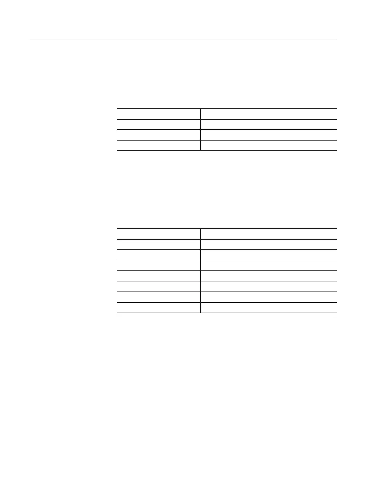
Signal at PROBE COMP Possible problem
1 kHz signal, no display Go to Display Troubleshooting (Page 6–42)
No signal Go to Power Supply Troubleshooting (Page 6–40)
> 1.2 kHz signal Go to Power Supply Troubleshooting (Page 6–40)
Follow these steps to troubleshoot the power supply.
1. Remove the rear case using the procedure Rear Case on page 6–14.
2. Use the test oscilloscope to measure the voltages from the power supply
module at J131 on the main board module. The table below lists the voltages
you should expect to see.
Voltage at J131 Description
Pin 1 (marked with A ) +4.85 VDC to +5.15 VDC
Pin 2 +4.85 VDC to +5.15 VDC
Pin 3 GND
Pin 4 –4.35 VDC to –5.15 VDC (slightly higher if disconnected)
Pin 5 –23 VDC to –25 VDC
Pin 6 GND
Pin 7 1.4 V
pk-pk
to 5 V
pk-pk
, 47 to 63 Hz square wave
3. If all of the voltages are present, the main board is probably defective.
Replace it.
4. If all or some of the voltages are missing, continue with step 5.
5. Turn off the instrument and disconnect the cable at connector J131 on the
main board module.
6. Turn on the instrument and check the voltages at the loose end of the cable
disconnected from J131, checking for the same voltages as in step 2.
PROBE COMP Output
Power Supply
Troubleshooting

 Loading...


