Performance Tests
TDS 500B, TDS 600B & TDS 700A Performance Verification and Specifications
1–41
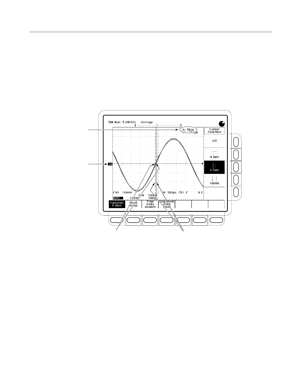
H Align one V bar cursor to the time reference point of the left-most
waveform edge and the other cursor to the time reference point of the
right-most waveform edge by rotating the General Purpose knob.
(Press SELECT to switch between the two cursors.) See Figure
1–11 on page 1–41.
H Read the measurement results at the D: cursor readout, not the @:
readout on screen.
Locate the time reference
points for these waveforms.
2
Display the waveforms.
1
Read results.
4
Align each cursor to the time
reference points
3
Figure 1–11: Measurement of Channel Delay – TDS 684B Shown
g. Check against limits: CHECK that the cursor readout on screen is
≤100 ps for the TDS 600B or ≤50 ps for the TDS 500B/700A.
h. If the channel skew is within the limits, enter time on the test record and
proceed to step 3. Otherwise, proceed with steps i through p.
i. Use the cursors to measure the skew from CH1 to CH2, CH1 to CH3,
and CH1 to CH4 (use AX1 and AX2 instead of CH3 and CH4 if your
TDS model is so equipped). Write down these three numbers in the first
measurement column of Table 1–5. Note that these numbers may be
either positive or negative.

 Loading...


