Performance Tests
1–62
TDS Family Performance Verification and Specifications
Equipment
Required
One female BNC to clip adapter (Item 3)
Two dual-banana connectors (Item 6)
One BNC T connector (Item 7)
Two 50 precision cables (Item 5)
One DC calibration generator (Item 9)
Prerequisites See page 1–15. Also, the Digitizing Oscilloscope must have passed
Check Accuracy For Long-Term Sample Rate, Delay Time, and Delta
Time Measurements on page 1–43.
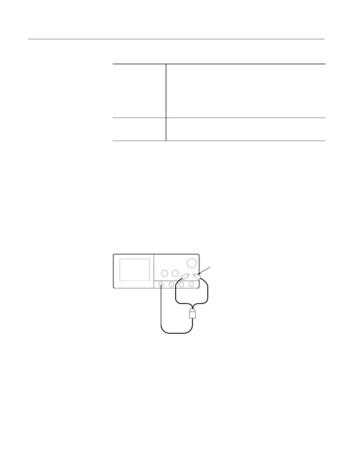
1. Install the test hookup and preset the instrument controls:
a. Hook up test-signal:
H Connect one of the 50 W cables to CH 1. See Figure 1–22.
H Connect the other end of the cable just installed to the female
BNC-to-clips adapter. See Figure 1–22.
H Connect the red clip on the adapter just installed to the PROBE
COMPENSATION SIGNAL on the front panel; connect the black
clip to PROBE COMPENSATION GND. See Figure 1–22.
Digitizing Oscilloscope
50 Coaxial Cable
Female BNC to
Clip Adapter
Black Lead
to GND
Figure 1–22: Initial Test Hookup
b. Initialize the oscilloscope:
H Press save/recall SETUP.
H Press the main-menu button Recall Factory Setup.
H Press the side-menu button OK Confirm Factory Init.
Check Probe
Compensator Output
 Loading...


