Performance Verification
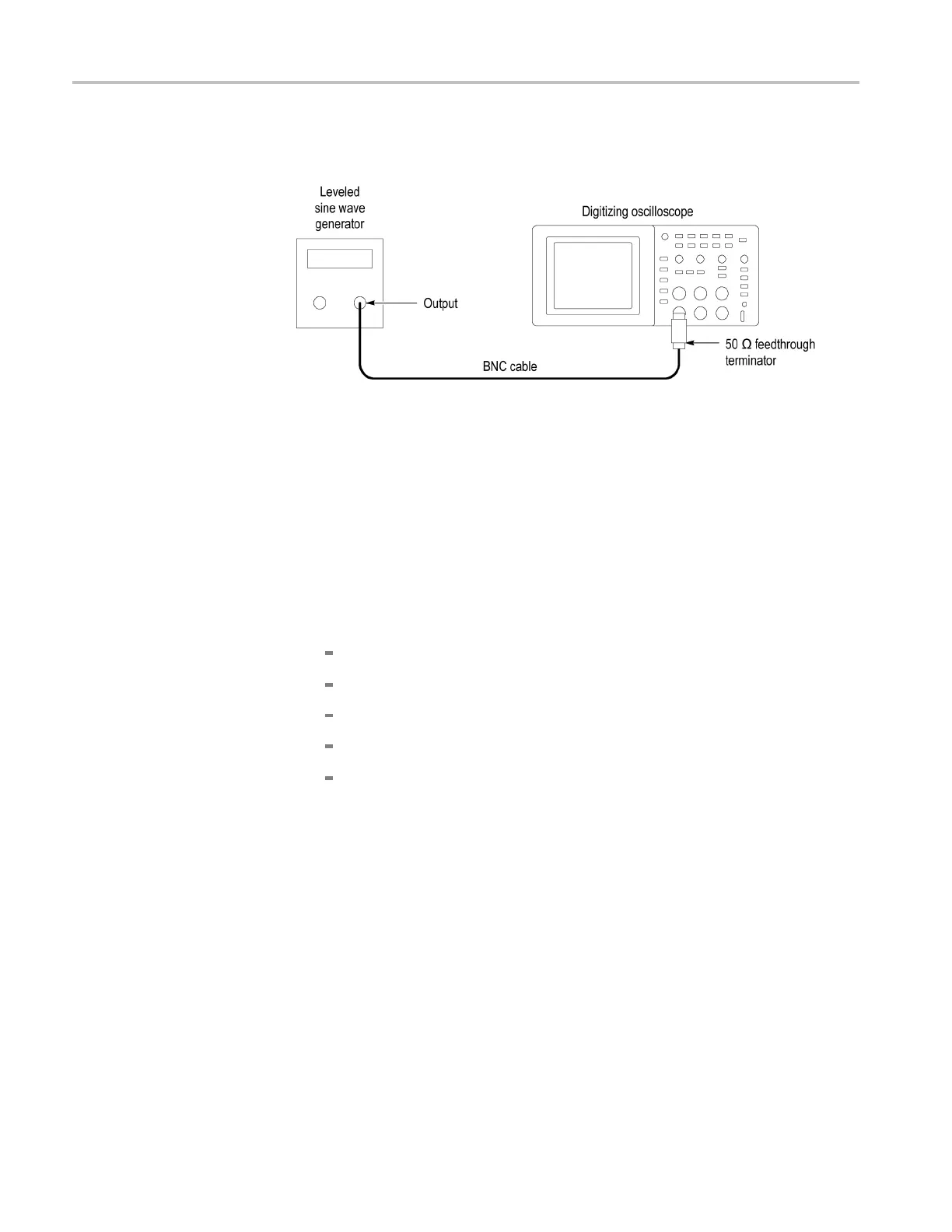
2. Connect the osc
illoscope channel under test to the leveled sine wave generator
as shown in the following figure:
3. Set the oscilloscope Vertical Scale (volts/division) to 500 mV/div.
4. Set the oscilloscope Horizontal Scale (seconds/division) to 25 ns/div.
5. Set the leveled sine wave ge nerator fre quency to 10 MHz.
6. Set the leveled s ine wave generator output level to approximately 500 mV
p-p
so that the measured am plitude is approximately 500 mV.(Themeasured
amplitude can fluctuate around 500 mV.)
7. Push Set To 5 0%. Adjust Trigger Level as ne ces sary and then check that
triggering is stable.
8. Set the leve le d sine wave g ene rator frequency to:
40 M Hz if you are checking a TDS1001C-EDU
50 M Hz if you a re checking a TDS2001C
60 M Hz if you are checking a TDS1002C-EDU
70 MHz if you are checking a TDS2002C, or TDS2004C
100 MHz if you are checking a TDS1012C-EDU, TDS2012C, TDS2014C,
TDS2022C, or TDS2024C
9. Set the oscilloscope Horizontal Scale (seconds/division) to 5ns/div.
10. Set the leveled sine wave generator output level to approximately 750 mV
p-p
so that the measured amplitude is approximately 750 mV.(Themeasured
amplitude can fluctuate around 750 mV.)
11. Push Set To 50%. Adjust Trigger Level as necessary and then check that
triggering is stable.
12. For the TDS2022C and TDS2024C models, set the frequency to 200 MHz,
and incr ease the amplitude to 1 V
p-p
. Verify stable triggering.
13. Set the oscilloscope Horizontal Scale (seconds/division) to 2.5 ns/div.
14. Change the oscilloscope setup using the following table:
34 TDS2000C and TDS1000C-EDU Series Oscilloscope Service Manual
 Loading...

