EasyManuals Logo

Tektronix TDS2022C User Manual

Tektronix TDS2022C
130 pages
To Next Page IconTo Next Page
To Previous Page IconTo Previous Page
Page #87 background image
Maintenance
6. Remove the four
screws that hold the Display Adapter board to the chassis
and save the screws for installation of the replacement board.
7. Loosen the Display Adapter board and disconnect the display cable at J201.
8. Remove the Display Adapte r board from the chassis.
Installation.
1. Connect the display cable to the Display Adapter board at J201. (See
Figure 6-3.)
2. Position the Display Adapter board on the instrument chassis and align the
board with the holes in the chassis.
3. Use the four screws that were removed to attach the Display Adapter board to
the chassis.
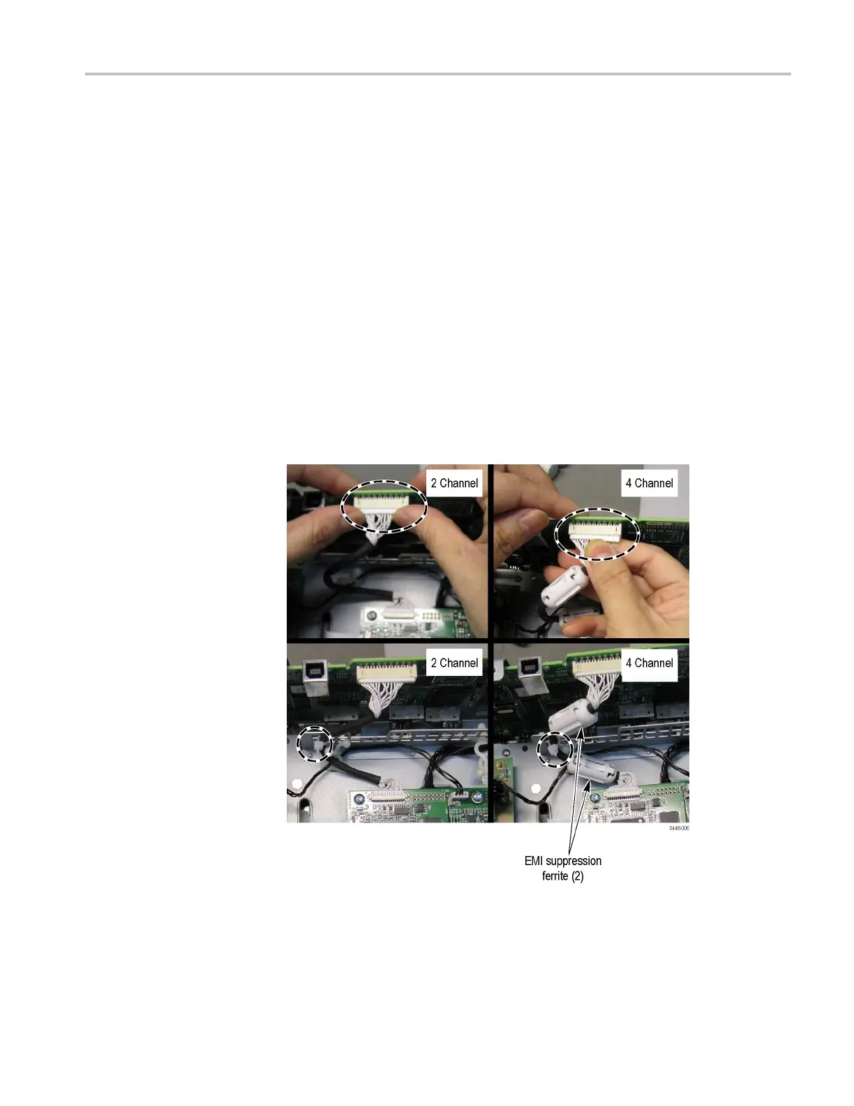
4. Connect the Display cable to J201 on the Main board as shown in the gure.
For the 4 channel models, make sure that the two ferrite EMI suppressors are
attached as shown. (See Figure 6-4.)
Figure 6-4: Connecting the Display cable
5. Attach the Display cable to the chassis with a cable tie as shown in the gure.
(See Figure 6-4.)
TDS2000C Series Oscilloscope Service Manual 6–15

Table of Contents

Other manuals for Tektronix TDS2022C

Questions and Answers:

Question and Answer IconNeed help?

Do you have a question about the Tektronix TDS2022C and is the answer not in the manual?

Tektronix TDS2022C Specifications

General IconGeneral
Bandwidth200 MHz
Sample Rate2 GS/s
Channels2
Record Length2.5 kpoints
Timebase Range5 ns/div to 50 s/div
Math FunctionsAdd, Subtract, Multiply, Divide, FFT
Input CouplingAC, DC, GND
Vertical Resolution8 bits
Trigger ModesAuto, Normal, Single
Memory Depth2.5 kpoints
Display5.7-inch color LCD
Input Impedance1 MΩ
Trigger TypesEdge, Pulse, Video
Display Resolution320 x 240 pixels
ConnectivityUSB
Automatic MeasurementsFrequency, Period, Rise Time, Fall Time
Power Supply100-240 VAC
Time Base5 ns to 50 s

Related product manuals