Installation Instructions
8
Acquisition Board Replacement
1. Remove the two screws nearest the front of the measurement set as shown in
Figure 3.
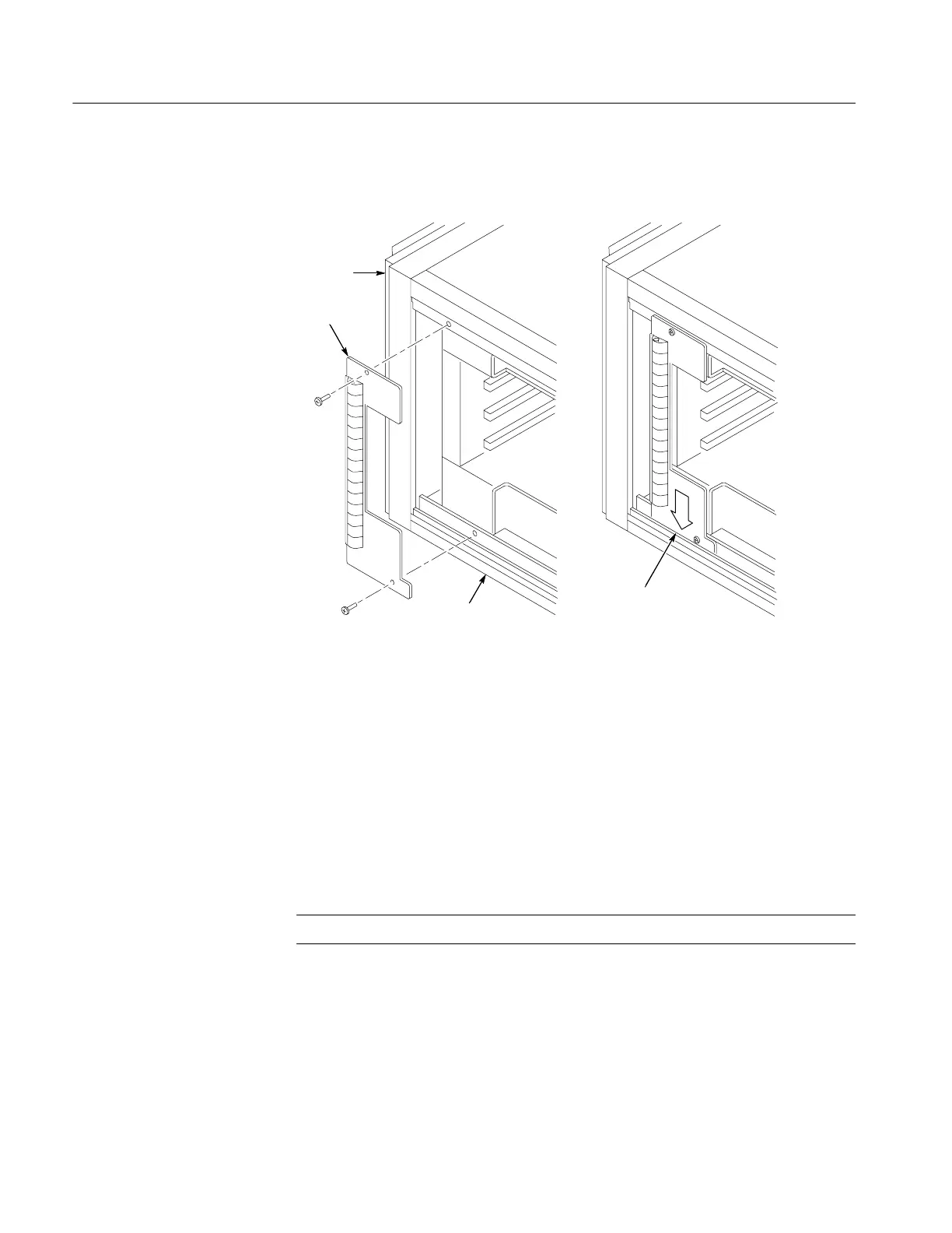
Front
EMI
bracket
Slide this end of EMI
bracket in place
Right side
Figure 3: Right side EMI bracket installation
2. Position the bottom edge of the EMI bracket (see right side of Figure 3)
inside the lower lip of the measurement set frame.
3. Align the EMI bracket to the screw holes in the measurement set. Attach and
tighten the two screws as shown in Figure 3.
4. Reinstall the circuit board retainer plate to the right side of the measurement
set as s hown in Figure 1.
5. Reinstall the right-side cover panel.
NOTE. If you do not have an I/O CPU (A20) board omit the next procedure.
1. Position the measurement set so that the left side faces you.
2. Remove the circuit board retainer bar from the left side of the measurement
set.
Right-Side
EMI Bracket
Circuit Board
Retainer Bar

 Loading...


