1. The two calibration methods are intended to give the installer two options for
calibrating the alarm.
2. Using the Alarm Point Capture method it is necessary to adjust the face velocity on
the fume hood using a mechanical damper ( or fan speed control if available) to the
desired alarm point and this is sampled by the unit. It is then necessary to re-adjust
the face velocity back to the normal operating value. This method produces a very
accurate alarm point at a fixed value but involves getting access to the ductwork or
fan speed controller
3. The second method of Two Point Capture is slightly more involved but does not
require any access to the ductwork or fan speed controller and is generally a quicker
solution.
The principal behind this method is as follows :-
The output from the airflow sensor is linear over the normal operating range of the
face velocities on fume hoods. If we therefore capture the airflow sensor output at
two known points we can then calculate the alarm point and give an alarm when the
airflow falls below this value. However because the AFA 500 does not have a digital
display of the face velocity we can not enter particular values into the alarm. For this
reason we take the normal operating value of the face velocity with the sash open to
the max safe working opening and call this 100% -- this point is captured during the
first sample. Then by closing the sash it is possible to create a face velocity which
is one and a half times the normal operating value ie 150% -- this point is captured
during the second sample. We then use these two values to calculate the sensor
output at 80% and this becomes the Low Air alarm point.
The actual value of the normal operating face velocity is not important and in each
case the alarm point will be 80% of this value.
For example:-
A normal face velocity of 100 fpm would give an alarm point of 80fpm
A normal face velocity of 80 fpm would give an alarm point of 64 fpm
4. The face velocity readings on the open sash may vary at different points on the
measuring grid by up to 20 fpm. This is quite acceptable in terms of the fume
cupboard performance so long as no individual point is below the designated Low
Air alarm point .The figure entered for the calibration point can be taken as the
average value of all the measuring grid readings or could be taken as the individual
lowest point on the grid. For most fume hoods this low point is on the bottom row in
the centre and is a convenient position to measure and for future reference when
checking the alarm during annual maintenance.
5. Take time when measuring the face velocities for the calibration procedure to allow
for the velocities across the open sash to stabilise. If the velocities are changing or
are turbulent during the sampling period the alarm will detect this and give a low
frequency buzz at the end of the sample indicating that the sample must be
repeated.
.
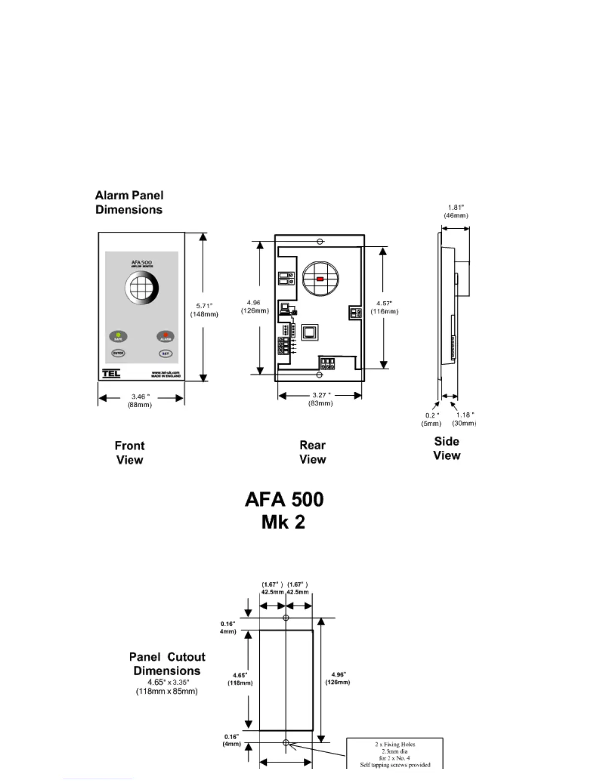
3.0 Dimensions
 Loading...