T1
T2
− MIC +
LS
− MIC +
LS
1
4
7
*
2
5
8
0
3
6
9 i
#
+
\
\
+MLM C +MLM B
MLM A
red blue yellow
Telephone line
analogue direct
extension line or
PBX extension
a wire
b wire
Relay 2
Relay contact rating:
60 VA 24 W max.
0.5 A 120 V AC or 1 A 24 V DC
NC
Com.
NO
Relay 1
Relay contact rating:
60 VA 24 W max.
0.5 A 120 V AC or 1 A 24 V DC
NC
Com.
NO
Alarm input
Alarm condition is
active while voltage is
applied
6 to 24 V DC
–
+
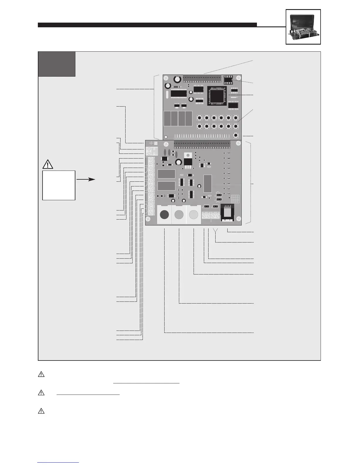
EEPROM
Master processor
Internal
configuration and
dialling keyboard
Earth
Main board
Connection board
Dial pad
Loudspeaker
Microphone
MLM A
(main MLM)
MLM B
(additional MLM)
MLM C
(additional MLM)
Program phone
number with
configuration step 22
Program phone
number with
configuration step 23
Program phone
number with
configuration step 24
Telephone ’ON’
Buttons
Make or break
contacts may be used
as nonlocking buttons
Call button 1
Common contact
Call button 2
+
–
Additional
power supply
12 V DC
potential-free voltage,
e.g. from Behnke plug-in
power supply
–
+
Connector for electronics
extensions
featuring a voice-announcement
facility, a clock or a display
20-0006
20-0018
Connect shield
for microphone
and buttons to
–12 V, not to
earth!
UNIVERSAL UNITS 20-0005/20-0006/20-0018
In order to connect MLM A to C (microphone/loudspeaker modules = user units comprising loudspeaker, microphone
and button), you should use original Behnke patch cables
.
The integr
ated add-on amplifier (1 W) can only be activated for MLM A. The corresponding configuration steps can be
found in our comprehensive technical manual (available as PDF on the Internet – see also note on page 2).
Connection of multiple MLMs reduces the maximum distance between MLM and basic electronics package:
1 MLM = 25 m / 2 MLMs = 12.5 m each / 3 MLMs = 10 m each
 Loading...