11
Standard settingEntry (code / parameter) Function
UNIVERSAL UNITS 20-0005/20-0006/20-0018
2
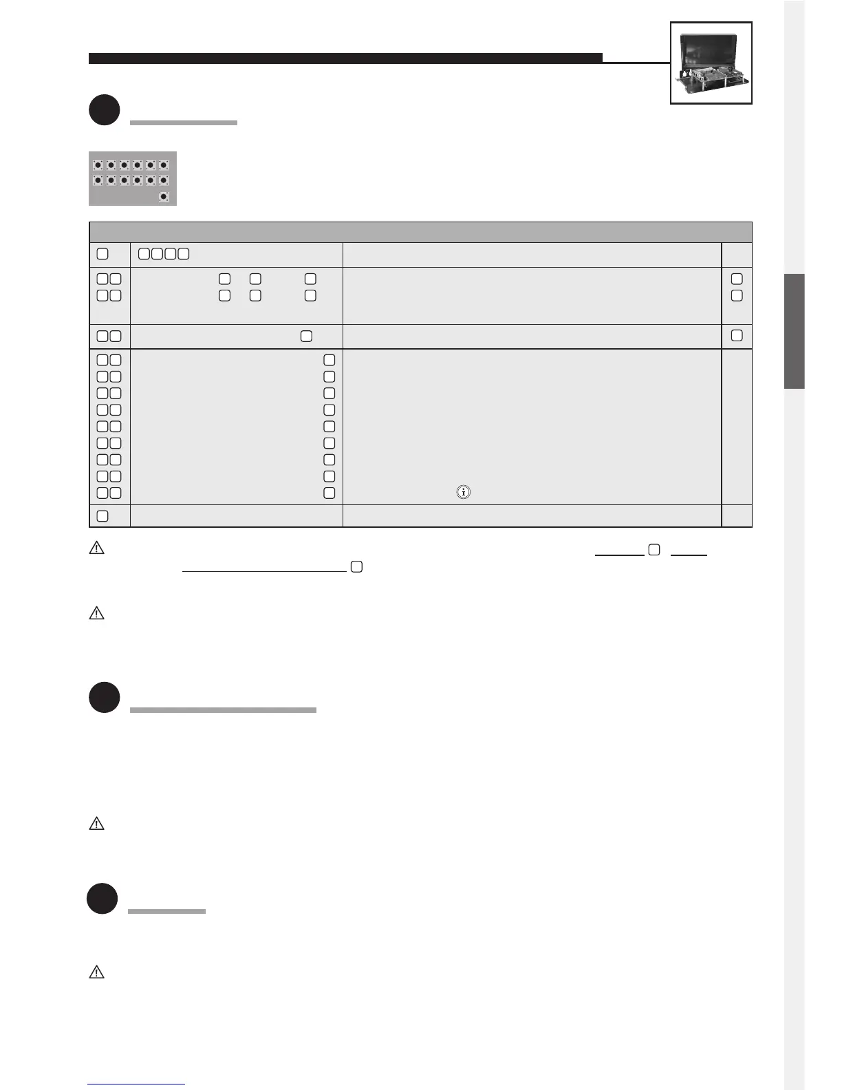
Configuration
Use internal configuration keyboard (open universal casing for this purpose).
Alternatively, configuration can also be done by DTMF telephone (touch-tone telephone).
Configuration is only possible with the a/b line (telephone line) connected.
• Mount the universal electronics package in a weather-proof location and connect it to the user unit(s).
• Observe the notes on cabling on pages 9 and 10 (25 m max., shielded cables, etc.).
• The connected buttons must meet the requirements of EN 60950 for telecommunications network voltages (TNV) circuits.
Normal bell push buttons do not usually meet these requirements; if required, use Behnke button 20-9100.
Further mounting information (with sample sketches) can be found in our comprehensive technical manual
(available as PDF on the Internet – see also note on page 2).
Following the entry of each phone number and other configuration steps, do not forget to pr
ess the - button!
In each case, finish configur
ation mode with . Otherwise it is possible that your entry is not stored correctly!
(factory setting) Enable configuration mode
A button from to , then Volume; 0 = low, 9 = high (full-duplex mode)
A button from to , then Volume; 0 = low, 9 = high (with add-on amplifier)
Note: Preferably use values between 1 and 4.
Number (4-digits max.), then Door-opener code (= 1st code for controlling relay 1)
Phone number to be dialled, then Phone number for 1 button —
Phone number to be dialled, then Phone number for 2 button or MLM A (yellow jack) —
Phone number to be dialled, then Phone number for 3 button or MLM B (blue jack) —
Phone number to be dialled, then Phone number for 4 button or MLM C (red jack) —
Phone number to be dialled, then Phone number for 5 button —
Phone number to be dialled, then Phone number for 6 button —
Phone number to be dialled, then Phone number for 7 button —
Phone number to be dialled, then Phone number for 8 button —
Phone number to be dialled, then Phone number for button of the dial pad —
End configuration mode
#
0 6 0 9
#
#
#
#
#
#
#
#
#
#
#
#
0
5
0
0
9
0 7
1 0
2 1
2 2
2 8
2 9
2 3
2 4
2 5
2 6
2 7
n
n
n
0 0 0 0
For further configuration steps (relay control, sound settings, voice-announcement/real-time clock extension electron-
ics), please refer to our comprehensive technical manual (available as PDF on the Internet – see also note on page 2).
The same operational notes apply as for Series 10 / Series 20 hands-free telephones (see page 8).
Further information on the operation of universal units (e.g. switching between several MLMs during a connection) can
be found in our comprehensive technical manual (available as PDF on the Internet – see also note on page 2).
3
Mounting / Installation
4
Operation
ENGLISH
 Loading...