EasyManuals Logo
Home>Telecom Behnke>Intercom System>10 Series

Telecom Behnke 10 Series Quick Reference Guide

Default Icon
23 pages
To Next Page IconTo Next Page
To Previous Page IconTo Previous Page
Page #12 background imageLoading...
Page #12 background image
12
UNIVERSAL UNIT 20-0007
AA
MM
EE
LL
AA
T89LT89L
V55V55
12J12J
II
00380038
T1
T2
T3
T4
T5
T6
T7
T8
T9
T10
T11
T12
T13
T14
T15
T16
T17
T18
T19
T20
T21
T22
T23
T24
T25
T26
T27
T28
T29
T30
T31
T32
gem.
Kont.
–+
MIC
LS
MIC
MT
V1.08a
–+
12345
67890#
T
E
L
#
Telefonbau Behnke GmbH
– 12 V +
REL. 1
REL. 2
+ ALARM
T1 T2
TEL
a / b
T1
T2
MIC +
LS
MIC +
LS
1
4
7
*
2
5
8
0
3
6
9 i
#
+
\
\
+MLM C +MLM B
MLM A
red blue yellow
Button 1
Common contact
(buttons)
Button 2
Button 3
Button 4
Button 31
Button 32
Optional dial pad
a/b
12 V=
Microphone
Loudspeaker
To 1st electronics extension 20-0057 (optional)
EEPROM
Master processor
Internal
configuration and
dialling keyboard
Telephone ‘ON’
Main board
Connection board
Subboard
Buttons 1 to 32
Terminals for relays 1
and 2 as well as alarm
input
(For details refer to connec-
tion sketch 20-0006.)
Note:
Do not use terminals
T1 and T2.
1
Connection
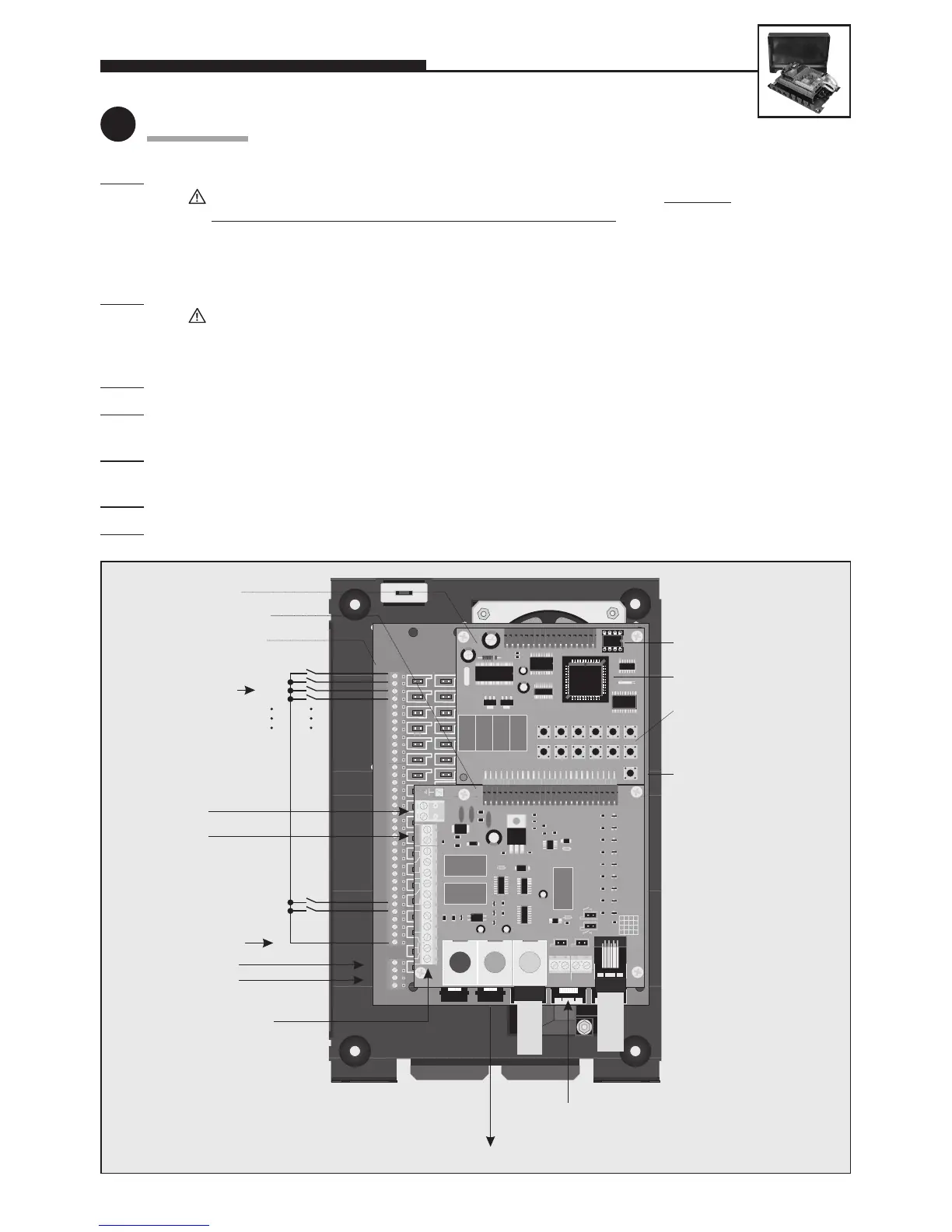
Step 1: Connect loudspeaker, microphone and buttons.
Distance of the loudspeaker, microphone and buttons from the basic unit: 100 m max
.
Buttons may hav
e a common return wire (applies only to 20-0007). To connect the basic electronics
package with the user-interface elements (loudspeaker, microphone and buttons) a shielded cable must
be used. IY-ST-Y or AY-ST-Y. Connect shield to –12 V terminal (see also Seite 2). Mount dial pad at a dis-
tance of 25 m max. (use Behnke patch cable for connecting the dial pad).
S
tep 2: Connect door opener to relay 1, if required.
Relay = voltage-free contact = only operates the door opener, without supplying it with electric energy;
the door opener requires its own power supply! Relay 2 is available for further switching functions
(see comprehensive technical manual; avalailable as PDF on the Internet).
S
tep 3:
Connect 12 V DC required for 20-0007 (potential-free – use Behnke plug-in power supply 20-9500).
S
tep 4: Release both short patch cables connecting the upper with the lower board from the RJ45 jacks on the
upper board.
S
tep 5: Connect telephone line (a/b line from analogue PBX extension or analogue direct exchange line) => a long
beep signals the telephone’s operational readiness.
S
tep 6: Perform configuration (item 2), while observing configuration step 18.
S
tep 7: Correctly plug back in again the patch cables into the RJ45 jacks on the upper board.

Other manuals for Telecom Behnke 10 Series

Questions and Answers:

Question and Answer IconNeed help?

Do you have a question about the Telecom Behnke 10 Series and is the answer not in the manual?

Telecom Behnke 10 Series Specifications

General IconGeneral
BrandTelecom Behnke
Model10 Series
CategoryIntercom System
LanguageEnglish

Related product manuals