6
SERIES 10 / SERIES 20
Use internal configuration keyboard (after removing the cover from the electronics casing).
Alternatively, configuration can also be done by DTMF telephone (touch-tone telephone).
Configuration is only possible with the a/b line (telephone line) connected.
Following the entry of each phone number and other configuration steps, do not forget to pr
ess the button!
In each case, finish configuration mode with . Otherwise it is possible that your entry is not stored correctly!
4.1 Series 10 / Home Office:
(factory setting) Enable configuration mode
A button from to , then Volume; 0 = low, 9 = high (full-duplex mode)
A button from to , then Volume; 0 = low, 9 = high (with add-on amplifier)
Note: Preferably use values between 1 and 4.
Number (4-digits max.), then Door-opener code (= 1st code for controlling relay 1)
Phone number to be dialled, then Phone number for 1 button —
Phone number to be dialled, then Phone number for 2 button —
Phone number to be dialled, then Phone number for 3 button (only Series 20) —
:: :
Phone number to be dialled, then Phone number for 8 button (only Series 20) —
Phone number to be dialled, then Phone number for button on the dial pad (only Series 20) —
End configuration mode
3
Configuration
4
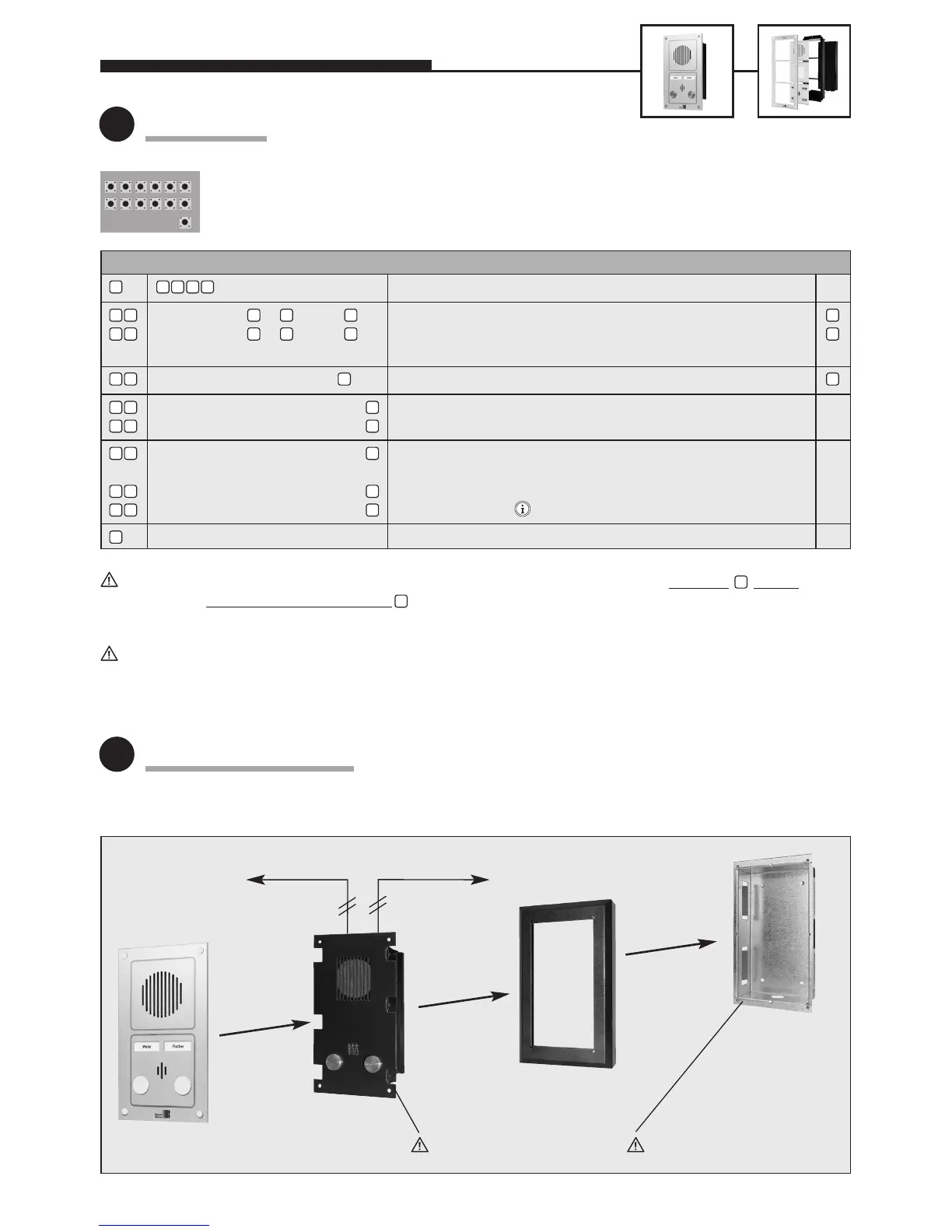
Mounting / Installation
#
0 6 0 59
#
#
#
#
#
#
#
#
0 0
0
9
0 7
1 0
2 1
2 2
2 8
2 9
2 3
n
n
n
0 0 0 0
For further configuration steps (relay control, sound settings, voice-announcement/real-time clock extension electron-
ics), please refer to our comprehensive technical manual (available as PDF on the Internet – see also note on page 2).
Telephone a/b
Flush-mounted
casing 10-5200
(accessory)
To door opener
Faceplate
Electronics
package
Insert gasket!
Surface-mounted
frame 10-5100
(accessory)
Insert gasket!
Standard settingEntry (code / parameter) Function
 Loading...