T8 T7 T6 T5 T4 T3 T2 T1 + MIC – + 12 V – + ALARM– LS
12345
∗
67890#
∗
T
E
L
#
Telefonbau Behnke GmbH
TEL
a / b
– 12 V +
REL. 1 REL. 2
+ ALARM – VIDEO
Anschluss für Elektronik-
erweiterungen
EEPROM
Masterprozessor
interne Konfigurations-
und Wähltastatur
Heizwiderstand
Verbindung
Anschlussplatine –
Subplatine
Anschlusskabel für
Module
Videoausgang
Alarmeingang
Relais 2
Zusatzversorgung
Telefonleitung
nur beschaltet in
Verbindung mit einem
Modul mit Kamera
Alarmzustand ist aktiv, solange
Spannung angelegt ist
Relaisschaltleistung:
max. 60 VA 24 W
0,5 A 120 V~ oder 1 A 24 V=
6 bis 24 V=
Relais 1
Relaisschaltleistung:
max. 60 VA 24 W
0,5 A 120 V~ oder 1 A 24 V=
12 V=
potentialfreie Spannung, z. B.
von Behnke-Steckernetzteil
analoger Hauptanschluss oder
Nebenstelle einer Telefonanlage
a-Ader
b-Ader
–
+
Ruhekontakt
Steuerkontakt
Arbeitskontakt
Videosignal
Video-Masse
–
+
Arbeitskontakt
Steuerkontakt
Ruhekontakt
Telefon „EIN“
Sprachansage, Uhr und Display
Hauptplatine
Anschlussplatine
Subplatine
Klemmen
Taste 1 bis 8
Mikrofon
nicht belegt
nicht belegt
Lautsprecher
RJ45-Buchse für
Tastwahlblock
Erde
T8 T7 T6 T5 T4 T3 T2 T1 + MIC – + 12V– + ALARM– LS
12345
∗
67890#
∗
T
E
L
#
Telefonbau Behnke GmbH
TEL
a / b
– 12 V +
REL. 1 REL. 2
+ ALARM – VIDEO
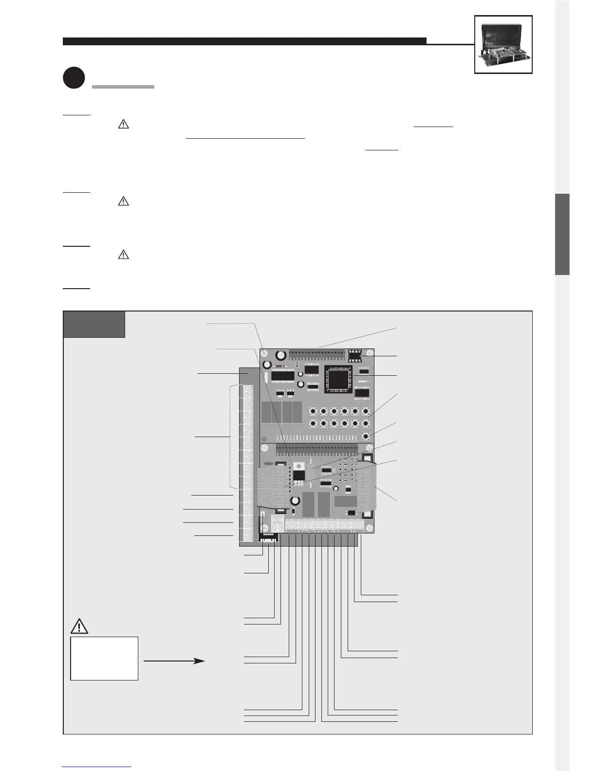
Connector for electronics
extensions
EEPROM
Master processor
Internal configuration
and dialling keyboard
Heating resistor
Connection-
board/subboard
connecting cable
Connecting cable for
modules
Video output
Alarm input
Relay 2
Additional power supply
Telephone line
only wired in connection with
a module with camera
Alarm condition is active while
voltage is applied
Relay contact rating:
60 VA 24 W max.
0.5 A 120 V AC or 1 A 24 V DC
6 to 24 V DC
Relay 1
Relay contact rating:
60 VA 24 W max.
0.5 A 120 V AC or 1 A 24 V DC
12 V DC
potential-free voltage, e.g. from
Behnke plug-in power supply
analogue direct extension line
or PBX extension
a wire
b wire
–
+
NC
Com.
NO
Video signal
Video earth
–
+
NO
Com.
NC
Telephone ‘ON’
featuring a voice-announcement
facility, a clock or a display
Main board
Connection board
Subboard
Terminals for
buttons 1 to 8
Microphone
unused
unused
Loudspeaker
RJ45 jack for
dial pad
Earth
UNIVERSAL UNITS 20-0005/20-0006/20-0018
1
Connection
20-0005
Step 1: Connect loudspeaker, microphone and buttons.
Distance of the loudspeaker, microphone and buttons from the basic unit: 25 m max
.
Buttons must not hav
e a common return wire. To connect the basic electronics package with the user-
interface elements (loudspeaker, microphone and buttons) a shielded
cable must be used. IY-ST-Y or
AY-ST-Y. Connect shield to –12 V terminal (see also page 2). Mount dial pad at a distance of 25 m max.
(use Behnke patch cable for connecting the dial pad).
S
tep 2: Connect door opener to relay 1, if required.
Relay = voltage-free contact = only operates the door opener, without supplying it with electric energy;
the door opener requires its own power supply! Relay 2 is available for further switching functions
(see comprehensive technical manual; avalailable as PDF on the Internet).
S
tep 3: Connect 12 V DC, if required (potential-free – use Behnke plug-in power supply 20-9500).
Only required for: illumination, camera, integrated heating, integrated add-on amplifier;
not required for: telephone operation, including all functions.
S
tep 4: Connect telephone line (a/b line from analogue PBX extension or analogue direct exchange line) => a long
beep signals the telephone’s operational readiness.
Connect shield for
microphone and
buttons to –12 V,
not to earth!
ENGLISH
 Loading...