EasyManua.ls Logo

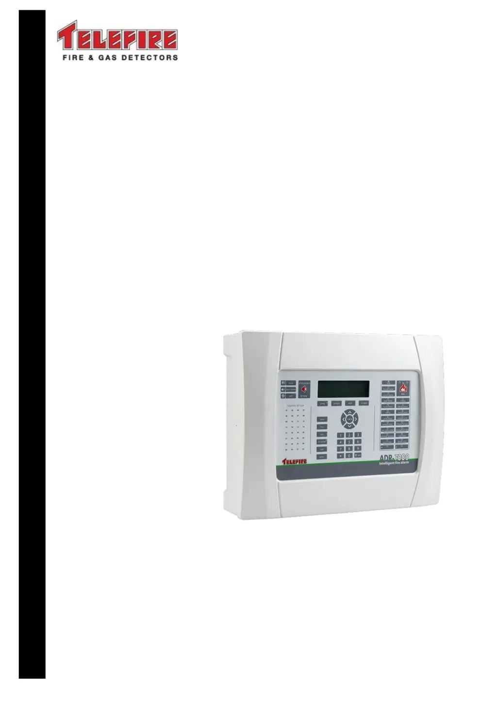
Telefire SAVER-7000 - User Manual

Default Icon
93 pages
Print Icon
To Next Page IconTo Next Page
Loading...
Control Panels
ADR-7000 / SAVER-7000 /
GUARD-7
Addressable
Fire Alarm Control Panel
Technical Manual
TELEFIRE FIRE & GAS DETECTORS LTD
PO Box 7036
Petach Tikva 49250
Israel
Tel: 972 3 970 0400
Fax: 972 3 921 1816
eMail: info@telefire.com
Web: www.telefire.com
ADR-7000En 98.pdf
Revision 0.98
October 2017

Table of Contents

Questions and Answers

  • A
    armstrongjenniferSep 3, 2025
    What causes ' output evacuation circuit is disconnected' on Telefire SAVER-7000 Control Panel?
    • D
      Dennis AllenSep 3, 2025
      If the Telefire Control Panel displays ' output evacuation circuit is disconnected', it means the output evacuation circuit is disconnected at the extinguishing controller. Reconnect the circuit.
  • T
    Thomas GainesSep 2, 2025
    What to do if Telefire SAVER-7000 says ' sirens circuit is disconnected'?
    • K
      Kevin LopezSep 2, 2025
      If the Telefire Control Panel displays an ' sirens circuit is disconnected' message, it indicates that the siren circuit is disconnected at the extinguishing controller. Reconnect the circuit.
  • S
    Shelley CampbellAug 31, 2025
    What does 'Panel # communication error' mean on Telefire SAVER-7000?
    • R
      Rebecca HurleyAug 31, 2025
      If the Telefire Control Panel displays 'Panel # communication error,' it means a control panel defined as a Partner is disconnected or powered off. Ensure that the control panel is on and verify the connection.
  • C
    Charles BriggsAug 29, 2025
    Why does my Telefire SAVER-7000 Control Panel show 'Main circuit limited current'?
    • C
      Christopher StevensonAug 29, 2025
      If the Telefire Control Panel displays 'Main circuit limited current' for a device, it means that the current has been limited on the designated device. Locate the source of the fault, such as damaged wire or a water leak, and repair it.
  • M
    Matthew WeberAug 27, 2025
    What causes 'Main circuit low voltage' on Telefire SAVER-7000 Control Panel?
    • D
      ddavisAug 28, 2025
      If the Telefire Control Panel displays 'Main circuit low voltage' for a specific device, it means the voltage is low on that device. If the device is the battery or backup battery (3V), replace the battery or backup battery (R2032C). Otherwise, the control panel may be faulty and should be sent to the manufacturer for repairs.
  • T
    Timothy BallardAug 26, 2025
    How to fix 'Main circuit short' on a Telefire SAVER-7000 Control Panel?
    • R
      Randy KellyAug 27, 2025
      If the Telefire Control Panel displays 'Main circuit short' for a device, it indicates a short circuit on that device. Find the cause of the short circuit and remove it.
  • H
    Haley LynchAug 25, 2025
    What does 'Main circuit disconnect' mean on my Telefire SAVER-7000?
    • H
      Heidi WalkerAug 25, 2025
      If the Telefire Control Panel shows 'Main circuit disconnect' for a specific device, it means that the designated device is disconnected. Check the line continuity and connect an end of line resistor (5.1K?) at the output circuit connectors.
  • J
    John GrimesAug 23, 2025
    How to enable a disabled device on Telefire Control Panel?
    • C
      Craig PonceAug 23, 2025
      If your Telefire Control Panel shows 'Disabled,' it indicates that a device or area has been disabled. To enable it: - Open the start/stop device menu from the main menu. - Select the device or area indicated in the message. - Click 'Enable'.

Summary

Work States - Alarm, Fault, Supervisory, Disablement, and Test Modes

Alarm State

Details the panel's behavior and indications during an alarm event, including operations.

Fault State

Explains how fault conditions are indicated, handled, and the actions taken upon confirmation.

Installation

Pre-Installation Planning

Guides on planning quantity, location of devices, and determining system requirements.

Pre-Installation Planning - Capacity Planning

Calculates required addresses, SLC loops, and control panels for system capacity.

Cable Planning

Covers planning for SLC, 24Vdc, and NAC cabling with various electrical considerations.

Cable Planning - SLC (Loop) Cable

Details planning for SLC loop cabling, including wiring configurations and cable types.

Cable Planning - SLC (Loop) Cable Selection

Provides guidelines for selecting SLC loop cable types and their maximum branch lengths.

Cable Planning - 24 Vdc Supply to Devices

Explains planning for 24Vdc supply cabling, focusing on voltage drop and operating values.

Cable Planning - 24 Vdc Supply to ADR-823 A Modules

Details using an LDO-7000 adaptor for 24Vdc supply to ADR-823A modules.

Cable Planning - NAC Outputs

Explains planning for NAC output cabling, considering voltage drop and device operation.

Cable Planning - Remote Annunciators

Covers cabling requirements for connecting RM-7000 remote annunciators via RS-485.

Cable Planning - LON-7000 Galvanic Networks

Details cabling for LON-7000 networks, including different topology options and wire types.

Cable Planning - LON-7000 Fiber Optic Networks

Explains using fiber optic connections for LON-7000 networks to overcome limitations.

Cabling Planning - ADR-7000 to TFP-3000 Firemans Phone

Details cabling requirements for connecting the Fireman's Phone system.

Pre-Installation Planning - Current Consumption and Battery Capacity

Guides on calculating current draw and determining battery capacity needs.

Pre-Installation Planning - Activation Matrices

Emphasizes planning activation logic as per consultant and local standards.

Pre-Installation - Releasing Planning

Covers the calculation of extinguishing device size and quantity by authorized personnel.

Installation of Detectors, I;O Modules, and Other Modules

Details the process of installing various system components and programming device addresses.

Site-Specific Configuration (Programming)

Covers site-specific data programming via software or auto-program methods.

Post-Installation

Covers final steps after installation: activation, field tests, verification, and documentation.

Automatic Extinguishing

Extinguishing Output and Extinguishing Controller

Explains configuring extinguishing outputs and controllers, and their unique properties.

Extinguishing Disconnect

Details the UL 864 requirement for a physical switch for extinguishing disconnect.

System Configuration (Programming) Process

System Configuration (Programming)

Enablement; Disablement

Covers enabling or disabling devices, zones, or main board outputs for specific operations.

Enabling and Disabling a Device

Explains the process for temporarily disabling individual devices or device types.

Enabling and Disabling a Zone

Explains disabling/enabling devices within a specific logical zone for operations.

Walk Test

Explains how to perform a walk test to verify all initiating devices of the system.

System Configuration

Covers configuring panel number, screen messages, partners, and other system settings.

Device Program

Explains manual and automatic device programming to set parameters for addresses.

Manual Device Programming

Allows manual setting of device parameters like loop, address, zone, and sensitivity.

Automatic Device Programming

Scans all addresses to map installed devices and configure them with default settings.

Change Passwords

Details how to change user and programmer passwords for system security.

Detector Initialization

Explains how to force detector initialization for new or changed detectors.

Troubleshooting

Control Panel Error Messages

Lists potential error messages, their meanings, and a note on the '#' symbol.

System Faults

Details system faults, their possible causes, and recommended repair actions.

Addressable Device Faults

Lists faults related to addressable devices, their causes, and appropriate repair actions.

Programming Faults

Describes common programming errors encountered and their solutions.

Compatibility

Input Devices

Lists addressable and conventional input devices compatible with the ADR-7000.

Connection via an Input Module

Lists conventional devices that connect via an input module.

Connection via a TRA-1 Adaptor and an Input Module

Lists devices that connect via a TRA-1 Adaptor and an input module.

Output Modules

Lists addressable and other output modules compatible with the ADR-7000.

Direct Attachment to the SLC Loop

Lists addressable output modules that can be directly connected to the SLC loop.

Connection via an Output Module or Directly to NACs

Lists devices connecting via output modules or directly to NACs.

Extinguishing devices

Lists various extinguishing device types and their corresponding adaptors.

Appendix C - Standards Compliance

UL 864 Compliance

Details the ADR-7000's compliance with UL 864 standards for fire alarm systems.

EN 54 - Options with Requirements

Lists ADR-7000 compliance with EN 54-2 and EN 54-4 mandatory functions and options.

EN 12094-1 Compliance

Details ADR-7000 compliance with EN 12094-1 for automatic extinguishing systems.

CP-10

Details ADR-7000 compliance with CP 10:2005 requirements, including specific features.

Telefire SAVER-7000 Specifications

General IconGeneral
Zones8
Enclosure MaterialMetal
Protection ClassIP30
StandardsEN54-2, EN54-4
Input Voltage230V AC
Battery Backup12V 7Ah
Relative HumidityUp to 95% non-condensing

Related product manuals