EN 3
REAR
L
R
FRONT
1
2
3
4
5
6
7
8
4
5 7
8
A
B
Installation/Connection
Basic Procedure
1. Remove the key from the ignition switch, then disconnect the
terminal of the car battery.
2. Make proper input and output wire connections.
3. Install the unit to your car.
4. Reconnect the
terminal of the car battery.
5. Reset the unit.
Warning
The unit can only be installed in a car with a 12 V DC power
supply, negative ground.
If you connect the ignition wire (red) and the battery wire (yellow)
to the car chassis (ground), you may cause a short circuit, that in
turn may start a fire. Always connect those wires to the power
source running through the fuse box.
Disconnect the battery’s negative terminal and make all electrical
connections before installing the unit.
Insulate unconnected wires with vinyl tape or other similar
material. To prevent a short circuit, do not remove the caps on the
ends of the unconnected wires or the terminals.
Be sure to ground this unit to the car’s chassis again after
installation.
If the power is not turned ON, the speaker wire may have a short-
circuit or touched the chassis of the vehicle and the protection
function may have been activated. Therefore, the speaker wire
should be checked.
Caution
If your car’s ignition does not have an ACC position, connect the
ignition wires to a power source that can be turned on and off
with the ignition key. If you connect the ignition wire to a power
source with a constant voltage supply, as with battery wires, the
battery may die.
Install this unit in the console of your vehicle. Make sure the
faceplate will not hit the lid of the console (if any) when closing
and opening.
After the unit is installed, check whether the brake lamps,
blinkers, wipers, etc. on the car are working properly.
Mount the unit so that the mounting angle is 30° or less.
If the fuse blows, first make sure the wires are not touching to
cause a short circuit, then replace the old fuse with one that has
the same rating.
Connect the speaker wires correctly to the terminals to which they
correspond. The unit may be damaged or fail to work if you share
the
wires or ground them to any metal part in the car.
When only two speakers are being connected to the system,
connect the connectors either to both the front output terminals
or to both the rear output terminals (do not mix front and rear).
Mounting and wiring this product requires skills and
experience. For safety’s sake, leave this work to professionals.
If you experience problems during installation, consult your
TELEFUNKEN dealer.
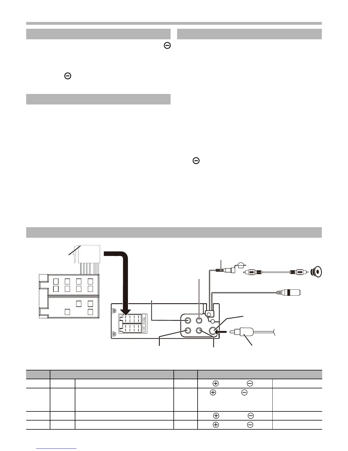
Wiring Connection
ISO Connector Wiring Chart
Pin Color and function Pin Color and function
A4 Yellow Battery (+) B1/B2 Violet
/Violet/Black Right rear speaker
A5 Blue Connect to system control terminal of the
power AMP or auto antenna relaycontrol
terminal (Max 150MA 12VDC)
B3/B4 Grey
/Grey/Black Right front speaker
A7 Red Ignition (ACC) B5/B6 White
/White/Black Left front speaker
A8 Black Ground B7/B8 Green
/Green/Black Left rear speake
Bluetooth External Mic Jack
FM/AM Antenna Socket
RCA to RCA Cable (not included)
Front RCA Output (Left)
Front RCA Output (Right)
Rear RCA Output (Left)
ISO Connector
(not included)
Antenna Jack (not included)Rear RCA Output (Right)
Subwoofer Output
 Loading...