EasyManua.ls Logo

Telesis BenchMark 200 User Manual

Telesis BenchMark 200
8 pages
To Next Page IconTo Next Page
Page #1 background imageLoading...
Page #1 background image
BenchMark
®
200/BM470 Marking System
34743A © 2011 –2012 Telesis Technologies, Inc. – All Rights Reserved 1 of 8
SYSTEM OVERVIEW
The Telesis
®
BenchMark
®
200 marking system permanently prints
messages into a variety of materials such as steel, aluminum, and
plastic. An electric solenoid accelerates a hardened pin to indent
dot matrix characters into the item being marked. Character shape,
size, density, and location are determined by the user through the
marking system software.
The BenchMark200 Marking Head is an electromechanical
marker. A thermo-formed cover houses the internal, mechanical
components that position the pin cartridge and fire the marking
pin. A spring returns the pin to its idle position within the
cartridge. The marking head moves the pin cartridge through X-
and Y-axis motions to reach the correct position for each dot of
the characters to be marked. The system software automatically
controls pin extension to mark the message.
The marker uses two stepper-motor drives to rapidly and
accurately position the pin at coordinate-defined locations in the
marking window within 0.032 mm (0.00125 in.). The marker
accommodates the rigorous dynamics of impacting, rebounding,
and rapid positioning of the marking pin through a system of rigid
rails and ball bearing saddles, timing belts, and direct-drive,
toothed pulleys.
The pin design permits high quality, consistent marks on irregular,
slightly curved surfaces. It also accommodates applications where
marking surfaces cannot be positioned at a consistent distance
from the marker.
The Marker Cable connects the marker to the BM470 Controller.
The cable is 4 m (13 ft.) long and is pre-wired to the marking
head.
The Pin Cartridge, machined from engineered plastic materials,
offers long life with little maintenance. Screws attach the pin
cartridge to the marking head for easy removal, cleaning, and pin
replacement.
The 25XLE-series Marking Pins are made of tungsten carbide
and are available in 30° and 45° cone angles.
BM470 Controller contains an integrated keyboard with an LCD
display. It provides a text-only operator interface and allows full
operational control of the marking head. The back panel provides
an electrical interface for connecting optional, remote I/O sources.
Refer to BM470 Controller Specifications for details.
The Tool Stand holds the marking head and provides a base for
securing parts to be marked. It uses a screw jack with an
adjustment wheel to position the marker above the marking
surface. Adjustment locks secure it in place. The generous
vertical adjustment accommodates parts up to 298.4 mm
(11.75 in.) high. The tool stand base contains slots to
accommodate part fixtures. The tool stand comes with two 8mm
T-nuts to aid in securing the parts for marking..
BenchMark200/BM470 Marking System General Arrangement
Question and Answer IconNeed help?

Do you have a question about the Telesis BenchMark 200 and is the answer not in the manual?

Telesis BenchMark 200 Specifications

General IconGeneral
BrandTelesis
ModelBenchMark 200
CategoryIndustrial Equipment
LanguageEnglish

Summary

System Overview

BenchMark200 Marking Head Description

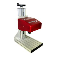
Details the electromechanical BenchMark200 marking head, its components, and operation.

BM470 Controller Description

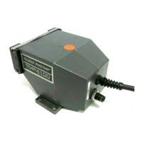
Describes the BM470 controller with integrated keyboard, LCD display, and operator interface.

Tool Stand Description

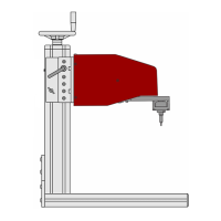
Explains the tool stand's function to hold the marking head and position parts for marking.

Marker Cable and Pin Cartridge

Information on the marker cable connecting the head to the controller and the pin cartridge.

System Options

System Setup

BenchMark200 Marking Head Specifications

Marking Characteristics

Details character size range, rotation, and printing resolutions for marks.

Marking Speeds and Depth

Covers marking speeds and the achievable marking depth in various materials.

BenchMark200 Marking Head Dimensions

Marking Noise and Pin Life

Marking Noise

Discusses sound pressure levels during operation and factors affecting noise.

Pin Life

Information on the expected life of marking pins based on material and depth.

BenchMark Tool Stand Specifications

Tool Stand Dimensions

Provides detailed dimensions for the BenchMark Tool Stand assembly.

BM470 Controller Specifications

Controller Dimensions

Details the physical dimensions and port layout of the BM470 controller.

Input Signals

Describes the available input signals for controlling the marking system.

BM470 Controller Environmental and Interface

Environmental Considerations

Discusses installation considerations regarding contaminants and EMI.

Interface Panel Ports

Details the various ports on the controller's back panel for connectivity.

System Software

Pattern Management

Explains how the system software manages, stores, and edits user-defined patterns.

BM470+ Enhanced Communications

I/O Control Signals

Describes additional I/O signals for controlling patterns, printing, and system status.

Host Communications Protocols

Details communication protocols like Programmable and Extended for host interaction.

Host Communication Message Types

Explains different message types (1, P, Q, V, 0) for host-driven operations.

Extended Protocol Details

Extended Protocol Message Format

Specifies the SOH, TYPE, DATA, ETX, BCC, CR format for Extended Protocol communication.

Related product manuals