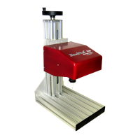
BenchMark 320/BM470 Marking System
34753A 7 of 10
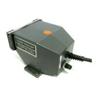
Interface Panel
The back panel of the BM470 controller provides
ports for connecting the marker and optional
accessories.
Marker Port. The Marker port connects the
BenchMark 320 marking head to the BM470
controller. It supplies the marking head with
electrical power and provides input and output
signals to and from the controller for marker
operation.
TTL Port. The TTL port is configured only for VDC
input. It allows the system to connect with a simple
contact closure circuit, such as a remote push
button station or foot pedal switch. These types of
devices can remotely control Start Print and Stop
(Abort) Print operations.
Comm Port. The Comm port allows connection to a
remote serial device. The Comm port can be used to
connect an optional customer-supplied PC to access
Telesis software utilities. Utility software can be
used to back up patterns stored in the controller,
download a custom font to the controller, or
download controller software upgrades. The Comm
port also allows you to connect an optional barcode
scanner. The software reads the scanned input and
inserts the data into a variable text field within the
currently loaded pattern.
USB Port. The USB port allows you to connect a
memory stick or flash drive for pattern storage or
retrieval and for software upgrades.
Auxiliary Axis Port (optional). The optional
Auxiliary Axis port is available only if the controller
is configured with the optional auxiliary axis circuit
card. This configuration allows connection to a
rotational drive unit to use the software Theta-axis
features.
System Software
The system software is permanently installed in the
controller and provides the user interface for the
operator to control the marker. The software also
provides a library for storing, loading, and editing
user-defined patterns.
Patterns are files stored in the controller’s memory.
Depending on the size of the pattern files, the
controller can store up to 200 patterns. Each
pattern contains one or more fields; each field
defines a single object.
Printable objects can be created to define text
strings, arc-text strings, geometric shapes,
graphics, and machine-readable data matrix
symbols.
Printable text fields can include alphanumeric
characters, symbols, and special message flags.
Message flags insert data, such as serial numbers,
times, dates and user-defined codes, into the text
string.
Non-printable objects can be defined to specify
commands for the marker to execute (for example,
Go To, Print, and Stop).
BM470+ ENHANCED COMMUNICATIONS
SOFTWARE
The optional BM470+ Enhanced Communications
software allows you to expand the controller’s
communication capability. It makes full use of the
available I/O port and allows you to configure the
Comm port communication parameters. See I/O
Control Signals and Host Communications.
I/O Control Signals
Additional input and output signals are available
through the I/O port only if the system uses the
optional BM470+ Enhanced Communications
software.
The I/O port is configured for 12 to 24 VDC I/O only
and can be used to connect a PLC or other DC I/O
source. The optically isolated I/O port allows you to
remotely select and load patterns, start and stop
printing, place the marker online, and monitor the
system output signals.
Cable connectors and connector pins for
constructing appropriate interface cables are
supplied with the controller.
Input Signals. Input signals provide the following
controls:
INPUT COMM..............For all inputs (+ or – supply)
START PRINT .............Begins the print cycle
STOP ........................Stops the print cycle
SEL_0 thru _6* ..........Remotely selects & loads up to
127* pattern files
SPARE_1, 2, 3............Three (3) spares for custom
applications
*
The system software allows the SEL_6 signal to be
configured for remotely selecting patterns or for
remotely placing the marker online. If used to place
the marker online, pattern selection is reduced to a
maximum of 63 patterns.
Output Signals. Output signals indicate the
following states:
OUTPUT COMM...........For all outputs (+ or – supply)
DONE .......................Print cycle is complete
READY ......................System is ready for message or
for start print command
PAUSED ....................System is paused (waiting
timeout or command)
NO FAULT .................System status (normal or fault
detected)
SPARE_1, 2................Two (2) spares for custom
applications
 Loading...