BenchMark 320/BM470 Marking System
2 of 10 34753A
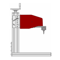
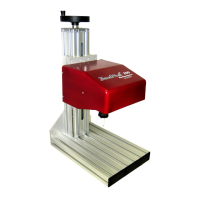
Tool Stand. The tool stand holds the marking head
and provides a base for securing parts to be
marked. A screw jack with an adjustment wheel
positions the marker above the marking surface.
Adjustment locks secure it in place. The generous
vertical adjustment accommodates parts up to
298.4 mm (11.75 inches) high. The tool stand base
contains slots to accommodate part fixtures. The
tool stand comes with two 8 mm T-nuts to aid in
securing the parts for marking.
SYSTEM OPTIONS
· Auxiliary Axis Driver Board Kit
· Motorized Theta-Axis with Programmable
Rotary Drive Unit
· BM470 Controller Wall-Mounting Bracket Kit
· Barcode Scanner or Barcode Wand with Cable
· Foot Switch (Start Print) or Push Button
Station (Start/Abort)
· Backup Utility Software
· Upgrade Utility Software
· Logo/Font Generator Software
· BM470+ Enhanced Communications Software
SYSTEM SETUP
1. Position the tool stand assembly in the
appropriate location.
2. Mount the marking head to the tool stand
assembly using four M8-1.25 socket head cap
screws. The screws must extend at least 9
mm (0.375 inch) but not more than 12 mm
(0.5 inch) into the back plate. Refer to the
BenchMark 320 Marking Head Dimensions
drawing for details.
CAUTION
The BM470 controller is not a sealed unit.
Protect it from potentially damaging
conditions and contaminants. Do not
block the vents in the bottom of the case.
Ensure the marking system is electrically
isolated from devices that may generate
extreme electromagnetic interference
(EMI).
3. Locate the controller as close as practical to the
marking head. Standard marker cable length is
4 m (13 feet).
4. Ensure the controller power switch on the back
panel is OFF. Connect the power cable to the
controller.
5. Connect the marker cable from the marking
head to the controller, and securely tighten.
6. To start the marking system software, position
the controller power switch on the back panel to
ON.
7. Adjust the pin stroke for proper pin impact
depth.
 Loading...