TMP1700/470 Marking System
2 of 10 28575G
SYSTEM SETUP
When designing a fixture, allow for 3-axis adjustment to aid in
horizontal, vertical, and lateral alignment of the marking head.
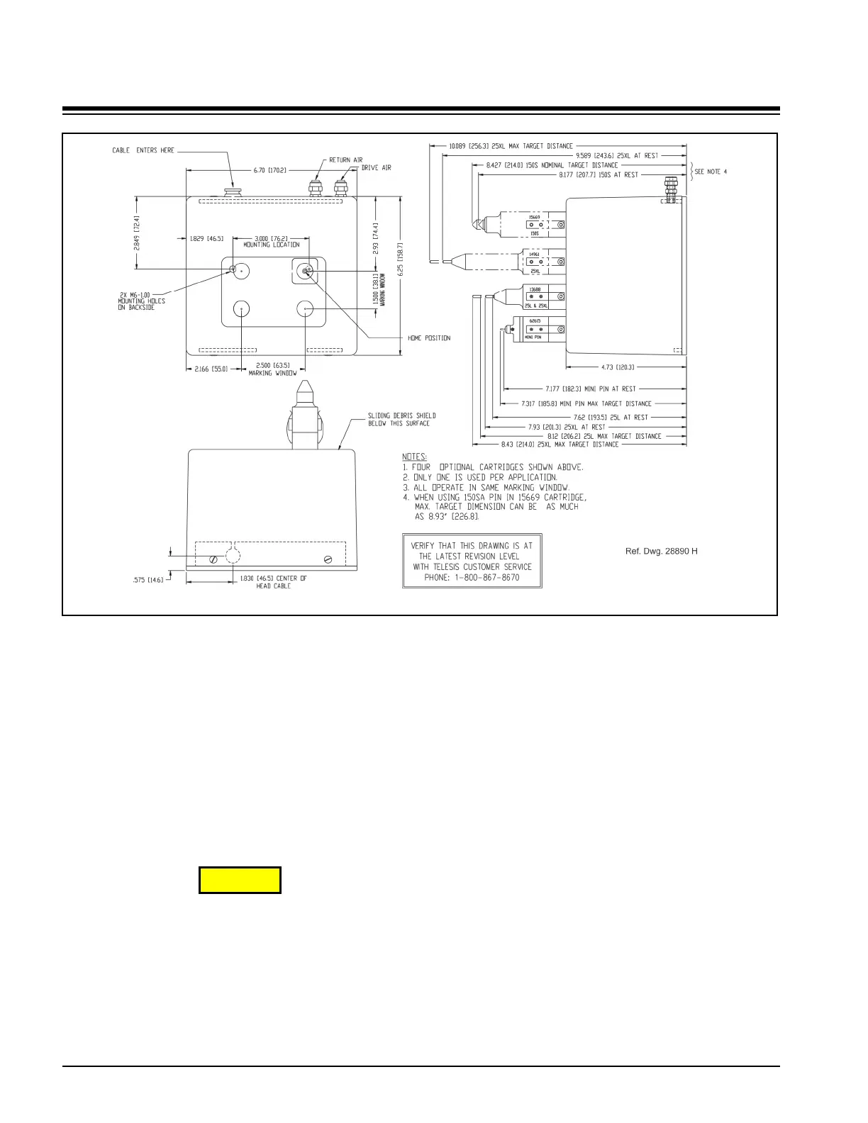
1. Mount marking head to optional tool post assembly (or
other suitable fixture) using two M6 bolts. Mounting bolts
must not extend into marking head more than more
5/8" (15 mm).
2. Mount filter/regulator assembly within 12 ft. (3.6m) of
marker.
3. Connect drive air and return air lines to the marking head.
4. Connect supply air to input port on filter/regulator
assembly.
CAUTION
The TMC470 is not a sealed unit. Protect it from
potentially damaging conditions and contaminants. Do not
block vents in bottom of case. Ensure the marking system
is electrically isolated from any devices that may generate
extreme electromagnetic interference (EMI).
5. Locate controller as close as practical to marking head.
Standard marker cable length is 4 m (13 ft.).
6. Install the controller as a table-top, wall-mounted, panel-
mounted, or enclosure-mounted unit, as applicable.
7. Ensure controller power switch is OFF.
8. Connect marker cable to controller.
9. Connect power cable to controller.
10. (optional) For systems that connect to a PC running the
Merlin III Visual Design Software:
a. Ensure PC power switch is OFF.
b. Connect cable to controller Ethernet Port and to PC.
c. Connect power cable to PC.
d. Position PC power switch to ON.
e. (customer-supplied PC) Install marking system
software.
11. Position controller power switch to ON.
12. Start marking system software.
13. Adjust pin stroke, drive air, and return air for impact
depth.
TMP1700 Marking Head Dimensions