Do you have a question about the Televes DATBOSSMIX LR and is the answer not in the manual?
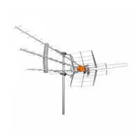
Insert UHF directors B1, B2, B3 into main assembly A and secure with bolts AA, AB, and nuts BA.
Move director booms to align horizontal elements on main assembly A for proper positioning.
Place plastic spacers E and F on director booms and secure with screws AG.
Mount clamp assemblies I onto support braces D using spacers H and tighten loosely.
Attach completed support brace assemblies to directors B1 and B3 using bolts AC and nuts BA.
Install self-locking clamp top piece O and bottom piece P onto main assembly A with bolt AD.
Place UHF reflectors G into self-locking clamps P, ensuring they seat fully and lock.
Attach metal plates N to the dipole T using bolts AF and nuts BC.
Install second rear receptor self-locking clamp P bottom piece and top piece O with bolt AD.
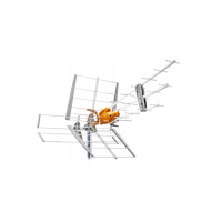
Mount orange plastic pieces M on VHF/BI Reflector Extension, using bolts AE and nuts BB.
Place Low-VHF reflectors S into orange plastic pieces M, secured with screws AH.
Join main antenna boom sections using Low-VHF assembly C and main assembly A, secured with bolt AB and nut BA.
Screw metal plates N to dipole ends using pieces L and screws AH, connecting to orange plastic pieces M.
Place VHF reflectors R into self-locking clamps, ensuring they seat fully and lock.
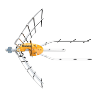
Release mast clamp shackles, mount antenna on mast, replace shackles and tighten nuts.
Terminate unterminated coaxial cable with weather boot and twist-on connector, pass through reflector.
Ensure longest boom is top, aim front TOWARDS towers, adjust elevation using mounting clamps.
Ensure system grounding for protection against surges and static charges per electrical codes.
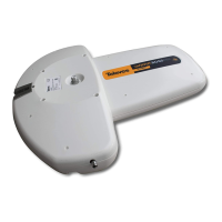
Avoid exposing power supply to moisture, stay clear of power lines, and do not alter the product.
Details gain, output level, power supply, consumption, weight, dimensions, and wind load for the active system.
| Frequency Range | 470-790 MHz |
|---|---|
| Channels | 21-48 |
| Polarization | Horizontal/Vertical |
| Connector | F-Type |
| Smart Technology | Yes |
| LTE Filter | Yes |
| Powering | Passive |
| Impedance | 75 Ohm |