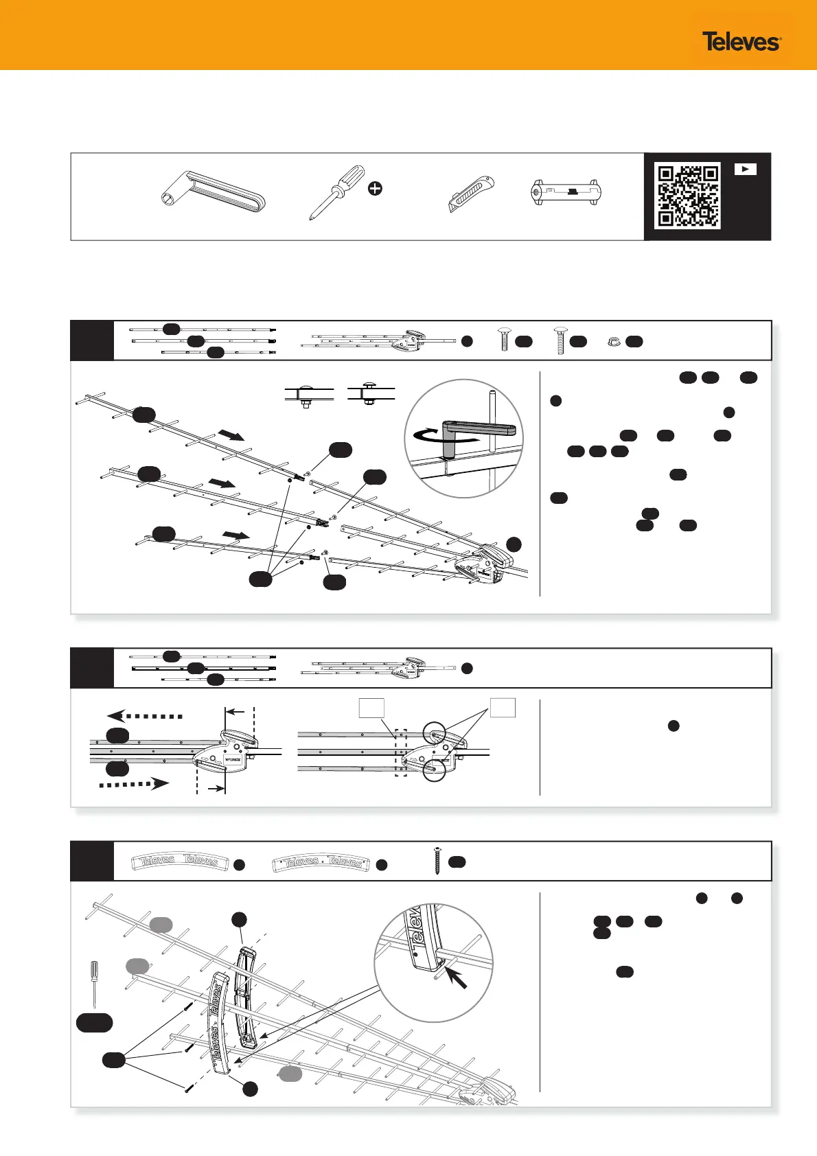
Antenna assembly / Montaje de la antena
1
3
2
A
A
B1
AA x2 AB BA x3
AG x3
B1
B2
B2
B3
B3
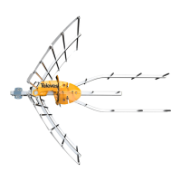
Proceed to insert UHF directors
B1
,
B2
and
B3
into the corresponding booms main assembly
A
by inserting the director end insert into the
corresponding location in main assembly
A
(“b1”
into “a1”, “b2” into “a2”, and “b3” into “a3”) then secure
them using bolts
AA
and
AB
and nuts
BA
.
The
B1
,
B2
,
B3
UHF directors are di erent sizes
and lengths so make sure to insert them in the right
positions, the longest director
B1
goes in the upper
position of the antenna and the shortest director
B3
goes in the lower position of the antenna.
Note: Tighten the nuts
BA
until the square carriage
heads of the bolts
AA
and
AB
sink into the
aluminum and the heads sit ush with the boom.
The bolt base will bite into the aluminum, securing
the joint.
Place plastic UHF director spacers
E
and
F
on
the director booms to match the screw holes of
director(s)
B1
,
B2
&
B3
elements. Secure them
with three
AG
phillips head screws.
Note: Be sure to place the spacers with the largest
opening (slot)
(1)
for the directors on the shortest
bottom director
B3
.
Move the top and bottom director booms
assembled in step 1 in the direction indicated by
the arrows on main assembly
A
until the horizontal
director elements of all three director booms line up.
B1
AA
AB
B1
B2
B3
B3
A
Note: Start the assembly procedure after thoroughly checking all parts and becoming familiar with them.
NEEDED
TOOLS
(a1)
(a2)
(a3)
(b1)
Included 10mm wrench Screw driver Cutter or Cable stripper
(b2)
(b3)
E F
F
E
PH #2
Scan to
watch
assembly
video
AA
AG
BA
(1)
PH #2
B1
B2
B3