9
10
11
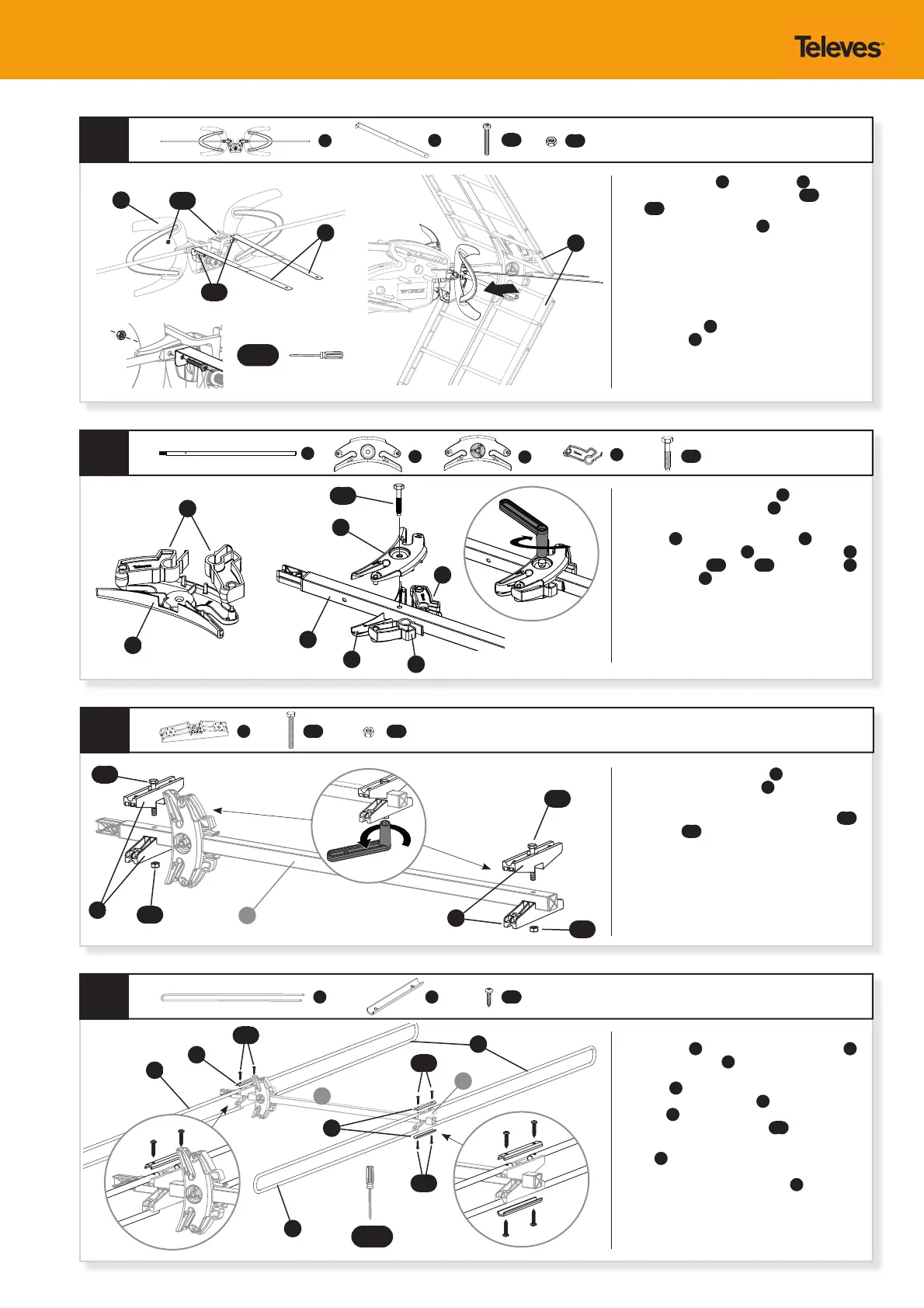
Mount the two black plastic locks
Q
on the second
rear receptor self-locking clamp
P
bottom piece.
Locate the mounting hole on VHF/BI re ector
extension
C
, place self-locking clamp
O
top piece
lined up with the hole in
C
and bottom piece
P
, secure with bolt
AD
(bolt
AD
goes through
O
and threads into
P
).
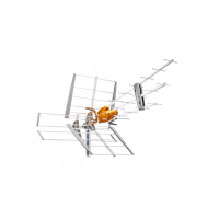
Mount the orange plastic pieces
M
on both ends of
the VHF/BI Re ector Extension
C
as indicated. They
must be lined up with the holes in it.
Fasten the assemblies with the use of the bolts
AE
and the nuts
BB
.
Starting at the rear of the antenna, place two Low-
VHF re ectors
S
into the orange plastic pieces
M
at the assembly end
C
with grey cap. Make sure
that the holes located at the end of the Low-VHF
re ectors
S
t into the plugs that you will nd
on the orange plastic pieces
M
. Place the metallic
jumpers
K
: one top, one bottom. Fasten the
assembly with the use of screws
AH
.
Repeat the same process with the orange plastic
pieces
M
at the other end toward the front, close
to the Re ector Self-locking Clamps. In this case, the
bottom ends of the Low-VHF dipole
S
will remain
loose until Step 13.
Q x2
O
M x4
S x4 K x3
P
Q
P
C
S
S
S
O
Q
Q
C
P
8
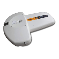
Attach metal plates
N
to the dipole
T
as shown
in the picture with the use of the bolts
AF
and the
nuts
BC
.
Insert the dipole assembly
T
into the antenna
orange junction box, sliding it through the guide
slot to the point where you will hear an audible
“click” indicating the dipole is latched into place and
fully seated in the main body of the antenna.
Visually check the dipole once installed to make sure
there are no gaps and that it did fully seat.
The metal plates
N
must be placed between the
UHF re ectors
G
without touching them.
M
C
M
T
CLICK!
T
N
G
N x2
K
K
AD
AD
AE
AE
BB
BB
AH
AH
AF
BC
AH
AE x2 BB x2
AH x6
AF x2
BC x2
PH #2
PH #2
M
C
 Loading...