2022 © Copyright, Televés S.A.U.
Televes USA LLC. Norfolk Tech Center 16596 E. 2nd Avenue Aurora, CO 80011 televes.usa@televes.com www.televes.com
Safety Instructions:
LIGHTNING PROTECTION
If installed outdoors, be sure the antenna system is grounded so
as to provide protection against voltage surges and built-up static
charges. Section 810 of the National Electrical Code ANSI/NFPA70, or
CSA C22.1 sections 10, 16, and 54, of the Canadian Electrical Code,
provide information with respect to proper grounding of the mast
and supporting structure, grounding of the antenna lead-in wire to
an antenna discharge unit, size of grounding conductors, location
of antenna-discharge unit, connection to grounding electrodes,
and requirements for the grounding electrode (see gure and
instructions).
Mount the lightning arrestor or 75 ohm coaxial grounding block as
close as possible to where the 75 ohm coaxial cable down lead enters
the house.
The ground wires for both the mast and the down lead should be
copper or aluminium wire, number eight (8) or larger.
The down lead wire from the antenna to the lightning arrestor and
the mast ground wire should be secured to the house, spaced from
four (4) to six (6) feet apart.
In the case of a “ground up” antenna installation it may not be
necessary to ground the mast if the mast extends four or more feet
in the earth. Consult a TV serviceman for the proper depth in your
location.
WARNINGS
To prevent re or shock hazard, do not expose the included power
supply to rain or moisture.
Installation of o-air antennas near power lines is dangerous. For
your safety, follow the installation instructions.
Any alteration or modication to the product or usage not in
accordance with product instructions voids the warranty.
Antenna Lead
in Wire
Example of antenna grounding as per
National Electrical Code, ANSI/NFPA 70
NEC - National Electrical Code
Ground
clamp
Electric Service
Equipment
Ground clamps
Power service Grounding Electrode System
(NEC Art 250, Part H)
Antenna Discharge Unit
(NEC Section 810-20)
(May substitute a 75 ohm
Coax Grounding Block)
Grounding Conductors
(NEC Section 810-21)
High-VHF
Antenna Selector
This antenna provides optimal reception
for the following zone(s)
Esta antena brinda recepción óptima para las siguientes zonas
See www.antennaweb.org for the list of broadcasters
in each reception zone where you live.
Consulte www.antennaweb.org para obtener una lista de
emisoras en cada zona de recepción donde Usted reside.
UHF
Antenna Selector
This antenna provides optimal reception
for the following zone(s)
Esta antena brinda recepción óptima para las siguientes zonas
See www.antennaweb.org for the list of broadcasters
in each reception zone where you live.
Consulte www.antennaweb.org para obtener una lista de
emisoras en cada zona de recepción donde Usted reside.
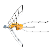
Technical specications of the intelligent antenna (it must be powered)
Características técnicas de la antena inteligente (debe estar alimentada)
Reference Referencia 148830
Operating band Banda de trabajo MHz
High VHF
174 - 216
CH7 - CH13
UHF
470 - 608
CH14 - CH36
Mode Modo INTELLIGENT (BOSS ON)
Gain Ganancia dBi 36.5 40
Output level Nivel de salida Auto*
Power supply Alimentación V
12
Consumption Consumo mA 70 (max) @12V
Beamwidth Ancho de haz º 60 40
F/B ratio Relación D/A dB
>20
Wind load Carga al viento N
96 (@ 80 mph)
132 (@ 93 mph)
* The gain is automatically adjusted
according to the level of output.
La ganancia varía automáticamente
en función del nivel de salida.
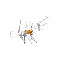
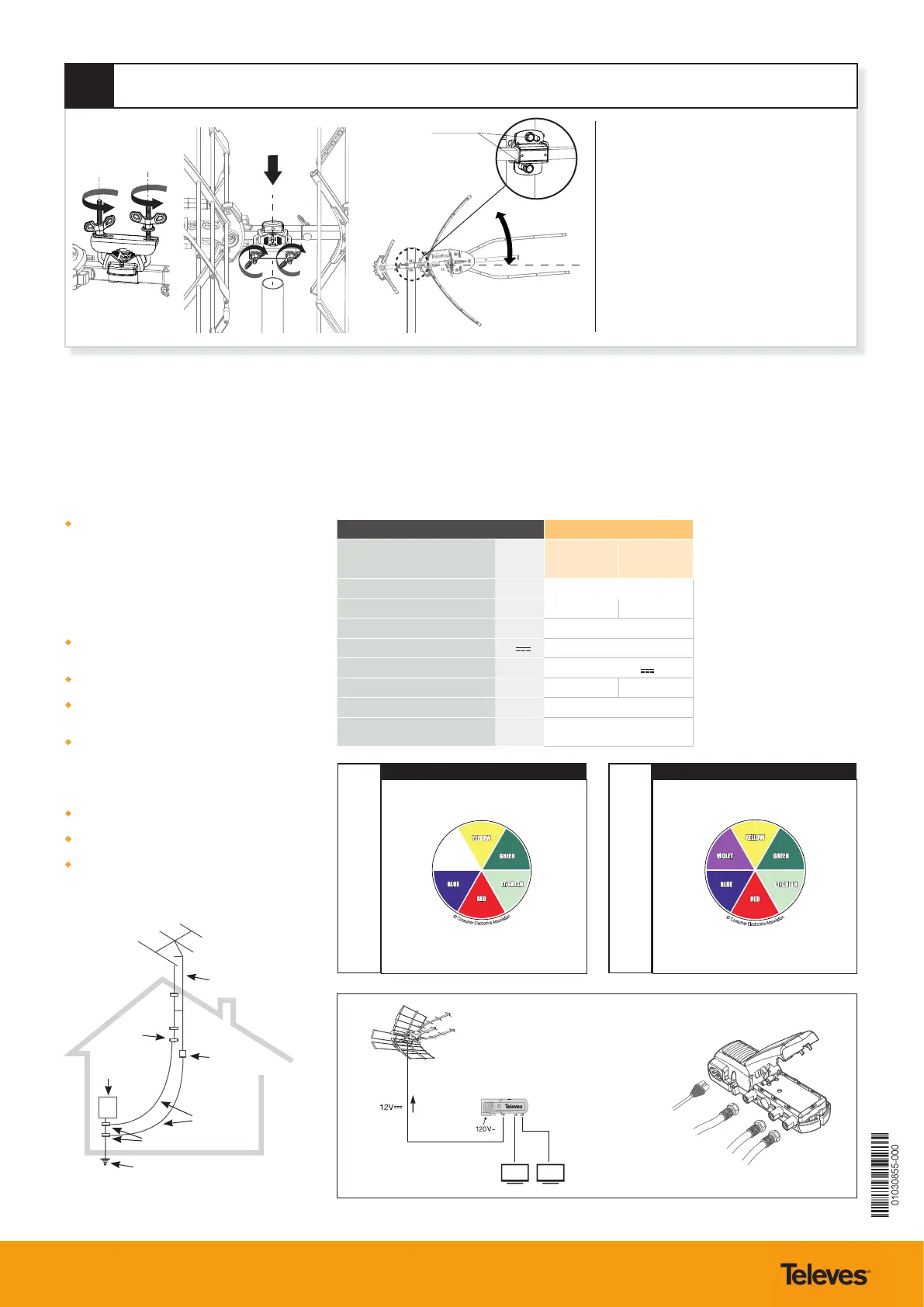
8
Release the shackles from the mast clamp by
removing and saving the wing nuts. Place the
antenna assembly on the mast (not included)
and proceed to replace the shackles and
tighten the wing nuts to attach the assembly
to the mast.
The “Tilt screws” will allow you to adjust the
antenna elevation (level, up or down to
optimize the installation). Be sure to tighten
these screws once the desired antenna
position is obtained.
Tilt screws
FINAL NOTES:
- Following the provided instructions, connect the included power supply to
the antenna using the leftmost connector (closest to wall power) with an
appropriate length of 75 ohm coax, RG-6 or larger is recommended. Make
sure than any device installed between the power supply and the antenna,
such as a splitter, is DC power passing. The two connectors on the right of
the power supply are for connecting your TV’s and/or coaxial distribution.
- When aiming the antenna it may be necessary to alternate adjustments
between left and right and then tilt, several times in order to achieve peak
signal reception for the largest number of desired channels.
- The antenna will work in an un-amplied, pass-through mode, if the power
supply is not connected or power fails to reach the antenna for any reason.
However, it is recommended to always use the antenna with power applied
in order to activate the industry leading, TForce automatic gain preamp that
is built in to the antenna.
- Always be sure to follow all local, state, and national electric codes. Seek the
assistance of a local professional if needed.
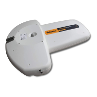
P.S.U. connections - 550104
*
(not included)
Mains power
from antenna
to TV 1
to TV 2
P.S.U
Ref. 550104
(included)
*
*
*
M10
 Loading...