LT910-WW User Manual - Telic AG
Pg 17
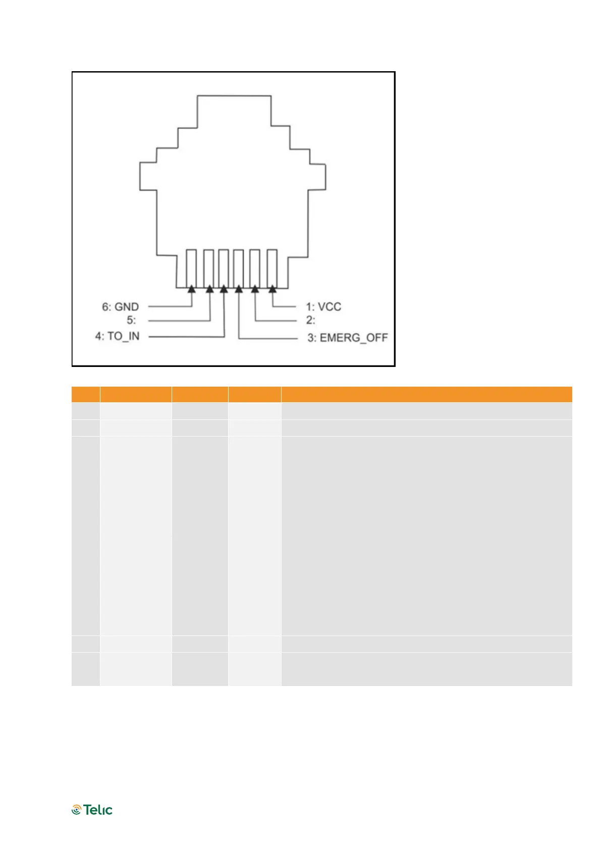
Figure 4: RJ11 Pin connector
Positive edge triggered signal to switch off modem
Only use after modem is fully switched on (PWRMON is
HIGH)
VIH > 5V, VIL < 0.5V
Power off: t > 3s
This signal triggers the command AT#SHDN
Positive edge triggered signal; used to switch on the
modem
VIH > 5V, VIL < 0.5V
Power on: t > 1s after VCC available
VIH = Voltage Input high
VIL = Voltage Input low
5 Not used
6 GND Input Negative power (ground) input and return path for TO_IN
and EMERG_OFF
Table 5: RJ11 Pin and signals description