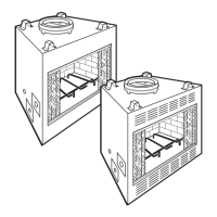
5. See figure 17 for offset calculation: Locate the center
point of the flue on the ceiling with a plumb bob as shown
on page 5. The center of the correct location for the
ceiling opening will be the amount of the offset dimen-
sion away from the ceiling nail. See figure 17. The "X"
dimension in the drawing is the amount of the offset. Be
sure to consider the direction that your offset will incline.
To achieve the minimum offset, (see table), attach the
return elbow to the first elbow. To achieve further offset,
you may install various lengths of pipe between the
elbows to a maximum length of 72 inches without a flue
support.
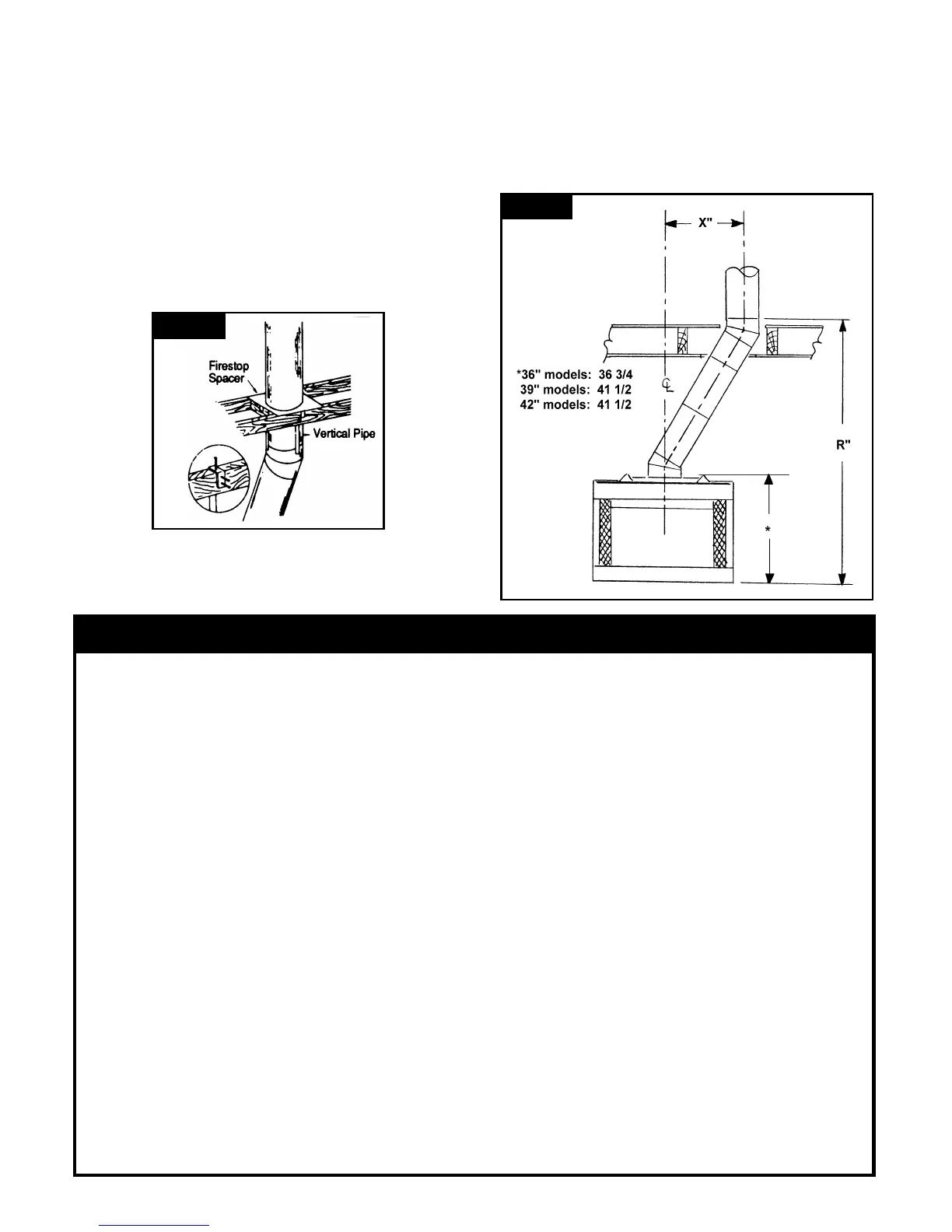
6. When the flue penetrates the ceiling at a 30° angle,
install firestop spacer 8230F. (See step 7 for
construction detail.)
Figure 16
Figure 17
Lineal Gain of Offset with Two Elbows
Components
Offset (ins.)
Dimension "X"
Rise (ins.)
Dimension "R"
Elbows only 3 7/8 14 5/8
Elbows with firebox 3 7/8 49 5/8
One 12" section 9 1/4 58 7/8
One 18" section 12 1/4 64
Two 12" sections 14 5/8 68 1/4
One 12" and one 18" section 17 5/8 73 1/4
Add to Add to
Two 18" sections 20 5/8 78 5/8
Components Dimension "X" Dimension "R"
One 36" section 21 1/4 79 5/8 12 " section 55 93
One 12" and one 36" section 26 5/8 88 7/8 18" section 83 14 1/2
One 48" section 27 1/4 90 36" section 17 3/8 30
One 18" and one 36" section 29 5/8 94 48" section 23 3/8 40 3/8
One 12" and one 48" section 32 5/8 99 1/4 Flue Support 17 29
One 18" and one 48" section 35 5/8 104 3/8
Two 36" section 38 5/8 109 5/8
One 36" and one 48" section
and one flue support 48 1/8 122 5/8
NOTES:
Rise dimension "R" (except for line 1, elbows only) in-
cludes firebox height (37 3/4 for 36" models, 41 1/2" for
39" and 42" models). If one of the elbows is not mounted
on the firebox as pictured in figure 17, subtract the appro-
priate amount from the "R" dimension in the table to get
the actual rise when elbows are mounted anywhere else
in the system.
If the required offset is not shown in this table, but is less
than the maximum allowed (125"), additional chimney
sections can be added to any of the listed combinations