Do you have a question about the Tempco tec-220 and is the answer not in the manual?
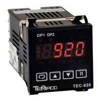
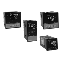
Introduces the TEC-220/TEC-920 controllers, their Fuzzy Logic and PID features.
Details the coding system for configuring TEC-220 and TEC-920 controllers.
Explains the function and usage of the programming port for configuration.
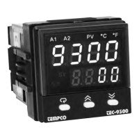
Describes the front panel keys and display elements for operating the controller.
Provides a flowchart illustrating the controller's menu structure and navigation.
Lists and describes various parameters available for configuring the controller's functions.
Instructions for unpacking the controller and checking for shipping damage.
Details panel cutout dimensions and mounting procedures for the controller.
Important safety and procedural guidelines to follow before performing wiring connections.
Guide for connecting the controller's power supply, specifying voltage requirements.
Recommendations for optimal sensor placement and selection for accurate control.
Wiring diagrams and instructions for connecting various sensor types to the controller.
Wiring diagrams for connecting control outputs to loads or contactors.
Wiring diagrams for connecting alarm outputs to drive loads or contactors.
Details on connecting the controller for data communication via RS-485 or RS-232.
Explains the four security levels for locking controller parameters to prevent unauthorized changes.
Describes how to select sensor types, units, resolution, and scale values for input signals.
Outlines the different control modes (Heat only, Cool only, Heat-Cool) and their setup values.
Details the six types of alarm functions and four alarm modes available for Output 2.
Instructions on how to configure the controller's display to show process value or set point.
Explains the ramping function for controlled setpoint changes during power-up or adjustments.
Describes how to configure Output 2 as a dwell timer for timed process operations.
How to shift the displayed process value to compensate for thermal gradients or sensor placement.
Details the programmable low-pass filter for stabilizing unstable process values.
Explains how outputs behave when the controller enters failure mode due to sensor breaks or A-D converter issues.
Guides users on performing auto-tuning for optimal PID parameter setup.
Provides methods for manual adjustment of PID parameters when auto-tuning is insufficient.
Instructions on how to enable and operate the controller in manual control mode.
Information on Modbus RTU communication via RS-232 and RS-485 interfaces.
How to retransmit the process value via analog outputs (TEC-220 only).
Example of using the controller for a heat-only application with a dwell timer function.
Example of using the controller for a cool-only application, focusing on ON-OFF control.
Example of a heat-cool application requiring both heating and cooling control actions.
Step-by-step guide for manually calibrating the controller's input and functions.
Describes the Modbus functions (03, 06, 16) supported by the controller and their message formats.
Explains how the controller responds to error messages and communication issues.
A comprehensive table listing all controller parameters, their addresses, scales, and read/write status.
Details the method for converting Modbus data values to actual parameter values.
Provides practical examples of Modbus communication messages for various controller operations.
Lists common error codes displayed by the controller and their corresponding corrective actions.
Outlines the terms and conditions of the Tempco product warranty.
Information regarding the process for returning products for service or repair.
Contact information and guidance for obtaining technical assistance and troubleshooting help.
| Display Digits | 4 |
|---|---|
| Control Mode | PID |
| Input Type | Thermocouple, RTD |
| Output Type | Relay, SSR |
| Display | LED |
| Resolution | 0.1°C |